
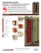
Instructions / Assembly


10
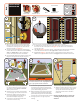
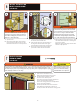
1. Using pliers, grasp handle
clip (H) and pull away from
latch rail to remove.
2. Fill holes in latch rail with
color matched plugs
included in installation kit.
1. Remove spacer clips (I) by loosening but not removing screws.
2. Re-tighten screws. TIP: Use a screw driver to loosen and tighten
screws; a drill driver may strip the screw holes.
3. Remove bottom spacer (J) by pressing down on raised lip.
4. Properly discard all orange clips.
d
e
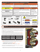
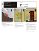
Your storm door lock can be changed (re-keyed) to match your main door’s
handle set if it’s a Kwikset® (included) or a Schalge® (additional purchase
required). Many home improvement stores or locksmiths can make
duplicate keys.
“Kwikset” is a registered trademark of Newfry LLC. “Schlage” is a registered trademark of Schlage
Lock Company.
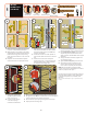
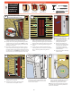
1. Install lock case trim plate onto lock case and
partially install 5/8” screw to allow movement.
2. Insert dead bolt key cylinder into lock case
and partially install 1 1/2” athead screw to
allow movement. Test deadbolt lock for proper
alignment.
3. Using a hand held screwdriver, tighten lock
case trim plate screws.
4. Tighten interior trim plate pan head screws.
5. Test handle operation. If handle does not
return to horizontal position, then lightly
loosen interior trim plate pan head screws.
NOTE: This door features an integrated latch
receiver in the latch rail, eliminating the need for a
traditional, separate strike plate.
1. Make sure the factory applied nylon washer
is in place at the base of both handles.
2. With trim plates not installed, insert handle
with spindle into outside exterior trim plate
(with Andersen logo) with lever pointing
down and rotate handle to secure it into the
trim plate.
3. Repeat for other handle without spindle
with inside interior trim plate (with slider).
c
i
VIEW
X
VIEW
H
J
I
2
3
1
2
a
DEAD BOLT
KEY CYLINDER
INTERIOR
TRIM PLATE
LOCK CASE
TRIM PLATE
Handle Clip Bottom Spacer
Color
Matched Plugs
Spacer Clips
H
J
I
INSTALL
HANDLE SET
(Right Hand)
10
5/8”
1-1/2”
x 2
1-1/2”
#8
#10
#12
#6
3/4” Machine Pan Painted
1/2” SMS Pan
1/2” SMS Pan Painted
1/2” SMS Flathead
1/2” Self-Drill Pan
1/2” Self-Drill Pan Painted
3/4” Machine Flathead
7/8” Machine Pan Painted
1” SMS Pan
1” SMS Pan Painted
1” Machine Pan Painted
1-1/2” Machine Flathead
1-1/2” Machine Flathead
2” SMS Pan Painted
5/8” SMS Pan Painted
1-1/4” SMS Pan
!
!
1/2”
1/2”
1/2”
1”
1 1/2”
2”
1 1/2”
5/8”
5/8”
!
!
1/2”
1/2”
1/2”
1”
1 1/2”
2”
1 1/2”
5/8”
5/8”
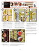
1. With handle levers held horizontal, install
both handle assemblies onto door. Spindle
will pass through square hole in lock case
and into other handle.
2. Install lock bar latch to lock bar. Spindle of
lock bar latch will t into the hole in the lock
bar.
3. Attach interior and exterior trim plates
together using two 1 1/2” pan head screws.
Partially install screws to allow movement
for alignment in following steps.
b
INTERIOR
TRIM PLATE
EXTERIOR
TRIM PLATE
LOCK
CASE
LOCK
BAR LATCH
LOCK BAR
2