
User`s guide

READOUT MODES
SDK SECTION 3
Page 28
SECTION 3 - READOUT MODES
INTRODUCTION
Andor systems are based on a detector known as a Charged Coupled Device (CCD). The detector is divided
up as a 2-dimensional array of pixels, each capable of detecting light. For example, systems based on an
EEV 30-11 CCD chip have 1024 X 256 pixels, where each pixel is 26µm
2
(all examples given in this manual
assume an EEV 30-11 based system). This 2-dimensional nature allows the device to be operated using a
number of different binning patterns. We refer to these binning patterns as Readout Modes.
Andor has several different readout modes as follows:
• Full Vertical Binning (FVB)
• Single-Track
• Multi-Track
• Random-Track
• Image
• Cropped
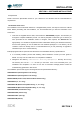
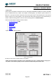
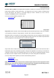
Figure 1 shows the binning patterns :
Figure 1: Binning patterns
We will now look at each of these modes in more detail.
NOTE: All of the patterns described can be simulated by the user in software but by carrying out
the pattern in the camera greatly increases speed and improves Signal to Noise ratio.