Product Manual www.andoveraudio.
Table of Contents Warnings / FCC Statement.........................................................4-5 Introduction / About........................................................... 6 In the Box / Room Placement............................................................7 Subwoofer Setup........................................................8, 9 Making the Initial Connections..........................................................10 Adjusting Level and Frequency..........................................
WARNING DO NOT OPEN TO PREVENT THE RISK OF ELECTRIC SHOCK, DO NO REMOVE COVER. NO USER-SERVICEABLE PARTS INSIDE. REFER SERVICING TO QUALIFIED SERVICE PERSONNEL. This symbol alerts the user to the presence of uninsulated “dangerous voltage” within the product’s enclosure that may be of sufficient magnitude to constitute a risk of electric shock to persons. Important Safety Instructions 1. Read these instructions. 2. Keep these instructions. 3. Heed all warnings. 4. Do not use this apparatus near water. 5.
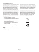
FCC STATEMENT FOR THE U.S.A. This equipment has been tested and found to comply with the limits of part 15 of the FCC rules. These limits are designed to provide reasonable protection against harmful interference in a residential installation.
Introduction Thanks for choosing the Model-One Subwoofer. Your Subwoofer is perfectly matched both sonically and aesthetically to the Model-One Turntable Music System. It may be used standalone with its beautiful tempered-glass top, or integrated with the Model-One stand system to create a full range music system with the smallest possible footprint.
In the Box • • • • • • • Model One Subwoofer Glass Top (Removable) AC Power Cord 1M signal cable with RCA plugs 2M signal cable with RCA plugs Leveling Feet (QTY - 4) Product Manual Room Placment The long wavelengths of low frequency sounds exceed the dimensions of most domestic rooms. With such long wavelengths, the sound reflected from the walls will reinforce bass in some places, and cancel bass in others. This is the result of “standing waves”.
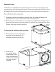
Subwoofer Setup Install the four adjustable feet in the four bottom corners of the subwoofer by screwing them into the threaded inserts. These may be adjusted slightly to level the subwoofer or stand if necessary once it is in its final location in your room. To use the Subwoofer separately: 1. Carefully remove the tempered glass top from the foam packaging and gently place it in the recess in the center of the top frame. 2.
3. Prepare the top stand by installing the 4 cam-lock pins into the innermost threaded holes. Screw them in fully, but do not overtighten. Also press the wooden alignment dowels fully into the larger adjacent holes. 4. Place the top stand on the subwoofer, being careful to align the pins into the proper holes. 5. Insert locking cams into each ofthe four holes and lock them by turning the cams clockwise until they stop. 6. Reinstall the grille by sliding it carefully from the front until it is fully seated.
Back Panel Power Inlet Power Power Mode Input (RCA) Volume Low Pass Making the Initial Connections 1. Connect the power cord into the AC power input connector and plug the other end into a grounded wall outlet. 2. Connect an RCA cable from the Subwoofer output of the source component into the RCA jack input. 3. Switch the power switch adjacent to the AC input ON. 4. Switch the Power mode switch to the AUTO (middle) position.
Adjusting Level and Frequency The centered positions of the level and frequency knobs represent the ideal starting point when the subwoofer is used with the Model-One Music System. It should provide an ideal match when the subwoofer is used as the lower section of the stand. If the subwoofer is placed separately from the stand, or if using a source other than the Model-One Music System, you may may need to adjust the settings away from the default.
Isogroove Technology Isogroove is our name for the suite of design features that reduce the generation and subsequent transmission of mechanical vibrations through the structure of the product. This reduces the liklihood they will be picked up by the turntable’s stylus, resulting in feedback. Andover products featuring Isogroove have been tested in a variety of locations and proven to be very effective when used as intended.
Two-Year Warranty Andover Audio warrants Model-One products against manufacturing defects and workmanship to the initial purchaser for a period of two (2) years from the date of delivery to customer. Andover Audio will repair or replace the unit as necessary to restore proper operation. This warranty covers both parts and labor for the warranty period. The warranty excludes physical damage caused by accident or abuse outside of our control. Or if the unit is damaged due to incorrect packing.
Specifications Type: Acoustic Suspension (Sealed) Enclosure ¾” MDF with internal bracing, Genuine walnut trim, and tempered glass top. Usable Frequency Range: 25Hz – 140Hz (High Frequency cutoff depends on Low Pass filter setting.) Power input: 3pin IEC connector Woofers: 2 x 10” Nominal Diameter with Polypropylene cones and 2” Voice Coils Power Requirement: 100-240VAC 5060Hz. Amplifier Power: 200W RMS Dimensions Input type: Monaural Line input. With top installed: 18” W x 13.5” D x 15.