
User's Manual

WLS Installation and Maintenance Manual Installation
Geometrix
®
Wireless Location System 16
Andrew Corporation Proprietary
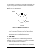
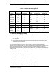
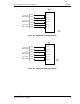
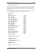
Table 2-1 WAN Cable Pin Assignment
Signal
Name
DB-25 pin
assignment
Winchester pin
assignment
Signal
Name
DB-25 pin
assignment
Winchester pin
assignment
Shield 1 A CTS 5 D
TxData(B) 14 S DSR 6 E
TxData(A) 2 P Ground 7 B
TxClk(A) 15 Y DTR 20 H
RxData(A) 3 R DCD 8 F
RxData(B) 16 T RxClk(B) 9 X
RTS 4 C TxClk(B) 12 AA
RxClk(A) 17 V
2.6 Alarm Cabling (optional)
1. Attach the alarm cable, part number G15A0497-1, to the DB-9 OPTION connector on the
rear of the WLS.
2. Cut the cable to the appropriate length and terminate on the base station alarm panel.
Terminal lugs may be required.
The alarm relay inside the WLS presents a set of Form C contacts at the WLS OPTION
connector. Under normal operation, the relay is energized and is released when an alarm occurs.
Pin 4 is normally open (NO), pin 2 is normally closed (NC), and pin 1 is alarm common (C).
Relay contacts are rated at 0.5A @ 125 VAC and 1A @ 24 VDC. The minimum permissible load
is 1mA @ 5 VDC.
The conditions that will generate an alarm are:
• The WLS is turned off
• The WLS unit is over the rated temperature
• The internal 10 MHz frequency reference is not present
• The internal clock phase locked loop is not locked
• A fault condition exists on a digital signal processor board
• An internal power supply voltage is over or under voltage