
User's Manual

WLS Installation and Maintenance Manual Installation
Geometrix
®
Wireless Location System 17
Andrew Corporation Proprietary
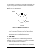
2.7 GPS Cabling
CAUTION: The WLS unit must be powered off before connecting or disconnecting GPS
cables.
1. Connect the GPS antenna cable to the GPS ANT port on the rear of the WLS unit.
2. If a GPS splitter is required:
a. Mount the splitter in the cable tray above the GPS receiver rack.
b. Disconnect the base station GPS receiver antenna input and attach to the splitter
ANT connector.
c. Install the supplied jumper cable between the base station GPS receiver antenna
input and the splitter BASE GPS port.
d. Install the supplied cabling between the WLS GPS ANT port and the splitter
E911 GPS port.
Verify proper base station GPS receiver operation locally in the base station and/or via the
Network Operations Center (NOC).
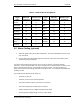
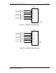
2.8 Antenna Cabling
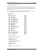
Connect the supplied cabling from the base station multicoupler receive antenna ports to the
WLS antenna input ports in accordance with Table 2-2. Notation is shown for up to four antenna
faces, alpha, beta, gamma and delta (A,B,G,D). The two receive antennas on each face are
designated 0 and 1.
For an omni-directional TDOA site only the two antenna ports set up for the alpha face would be
connected (ANT1, ANT5), while for a three sector TDOA site, the alpha, beta, and gamma faces
would be the only inputs connected (ANT1, ANT2, ANT3, ANT5, ANT6, and ANT7), leaving the
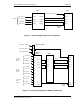
delta inputs (ANT 4 and ANT 8) unused. Note that in the case of a 4-channel WLS, ANT9,
ANT10, ANT11 and ANT12 connections are used instead of ANT5, ANT6, ANT7 and ANT8.
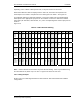
Figure 2-5 and Figure 2-6 illustrate antenna cabling for 2 and 4 channel TDOA sites respectively.
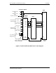
In the case of AOA, an RFDU is required to provide signal filtering and conditioning. If only one
AOA panel is used, connect the four antenna cables directly to the four RFDU input ports (A1 IN
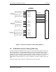
through A4 IN) as shown in Figure 2-7. For multiple AOA panels, an external antenna selector
switch is used. The four cables from each panel are connected to the appropriate sector inputs
(A1-A4, B1-B4 and C1-C4), and the output cables OUT 1 through OUT 4 are connected to the
RFDU input ports A1 IN through A4 IN respectively. The RFDU output ports A1 OUT through A4
OUT connect to the corresponding WLS antenna input ports (ANT1, 5, 9 and 13 for WLS4, ANT
1, 2, 3 and 4 for WLS4A). Figure 2-8 illustrates the multiple AOA panel configuration.
For AOA installations, an RF calibration source for AOA panels is provided in the WLS. Attach the
AOA panel calibration source cable to the WLS rear panel CAL SOURCE connector. For multiple
panel AOA installations, connect the calibration source cables from each panel and from the WLS
to the calibration source splitter as shown in Figure 2-8 .