
User's Manual

WLS Installation and Maintenance Manual Installation
Geometrix
®
Wireless Location System 18
Andrew Corporation Proprietary
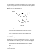
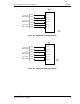
Depending on the number of AOA panels used, not all ports need to be connected.
Where both TDOA and AOA are employed at the same site, attenuators are required at the
TDOA inputs to the switch to compensate for the added gain of the RFDU. See Figure 2-9.
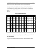
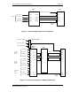
In installations utilizing the dual-band combiner, connect input cables from the individual band
multicouplers to the appropriate input ports on the combiner. Connect the dual-band combiner
output ports (A1 SUM OUT, A2 SUM OUT, etc.) to the corresponding WLS antenna input ports as
shown in
Figure 2-10.
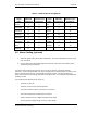
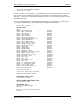
Table 2-2 WLS Antenna Cabling
Technology ANT1 ANT2 ANT3 ANT4 ANT5 ANT6 ANT7 ANT8 ANT9 ANT10 ANT11 ANT12 ANT13 ANT14 ANT15 ANT16
TDOA2
(WLS 2
model)
A0 B0 G0 D0 A1 B1 G1 D1 N/A N/A N/A N/A N/A N/A N/A N/A
TDOA4
(WLS 4
model)
A0 B0 G0 D0 N/C N/C N/C N/C A1 B1 G1 D1 N/C N/C N/C N/C
AOA (WLS
4 model)
A1
OUT
N/C N/C N/C A2
OUT
N/C N/C N/C A3
OUT
N/C N/C N/C A4
OUT
N/C N/C N/C
AOA (WLS
4A model)
A1
OUT
A2
OUT
A3
OUT
A4
OUT
N/C N/C N/C N/C N/C N/C N/C N/C N/C N/C N/C N/C
TDOA2
(Dual-band
Combiner
to WLS 2)
A1
SUM
OUT
B1
SUM
OUT
C1
SUM
OUT
N/C A2
SUM
OUT
B2
SUM
OUT
C2
SUM
OUT
N/C N/C N/C N/C N/C N/C N/C N/C N/C
TDOA4
(Dual-band
Combiner
to WLS 4)
A1
SUM
OUT
B1
SUM
OUT
C1
SUM
OUT
N/C N/C N/C N/C N/C A2
SUM
OUT
B2
SUM
OUT
C2
SUM
OUT
N/C N/C N/C N/C N/C
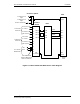
Note: Different AOA antenna versions may have different labeling. Ports may be labeled using
the nomenclature OL (Outer Left) or as Port 1. Figures are shown for each case.
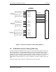
2.8.1 Cabling Examples
Please refer to the cable diagrams below for more detail for AOA and dual-band RF combiner
configurations.