
User's Manual


WLS Installation and Maintenance Manual Installation
Geometrix
®
Wireless Location System 27
Andrew Corporation Proprietary
The test is run over three frequency bands: Cellular A band, Cellular B band, and PCS band and
a results table is displayed for each band. Each test within the specified band is run ten times
(denoted by the iteration column above). If the test is run on a four-channel WLS, the test is run
on each of the two BPUs.
The test is a measure of BPU channel correlation when the same signal is injected into each of
the two channels on the BPU. The measure of correlation (listed in the test results as Rho) must
be greater than 0.98 to pass for Cellular band tests, and greater than 0.96 for PCS band tests.
The difference in the thresholds is due to lower signal source power in the PCS band, thus the
correlation between channels will be lower.
The RSSI is also measured on each channel (listed as pow_ch1 (dBm) and pow_ch2 (dBm)) and
must be greater than -105dBm to pass. In addition, the measured time difference between the
channels must be less than 50 nanoseconds (shown in the TOAdiff(ns) column in the table). This
is a short duration test only, and does not reflect the measurement accuracy obtained under
operational conditions, where measurement times are significantly longer.
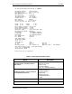
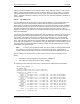
After the test has completed over all three frequency bands, an overall test result summary table
is displayed similar to the one shown below:
Band Pass? Required?
Cell_A YES YES
Cell_B YES YES
PCS NO NO
Test Result: PASS
The test software determines which bands are required to pass based on the BPU initialization
file (bpu.ini) on the WLS. In the above example table, only the cellular frequency bands are
required to pass the test. The overall test result is pass only if all required bands pass the test.
It is important to note that for a two channel WLS or a four channel WLS with an internal switch
(non-AOA) the test must pass for all bands, regardless of the band in which the WLS will be used
under normal operation. Multicouplers and filters external to the WLS will have no impact on the
results of this test. This is not the case for four channel AOA WLS’s, which are typically
configured with an external switch followed by an external RFDU. In this case only the RF band
passed by the RFDU is required to pass the test, since all other bands will be rejected by the
RFDU filtering.
On a two channel WLS or a four channel WLS with an internal switch, failure of any of these tests
would indicate an internal WLS fault somewhere between the antenna switch and BPU. These
units should be returned for repair.
On a four channel AOA WLS, there is typically an external switch connected prior to an RFDU,
which then connects to the WLS with RF jumper cables as shown in Figure 2-12. There is also a
control cable that runs from the WLS to the external switch. If the noise correlation test fails,
check the following items:
• Verify that the RFDU is powered on and that the green power light on the front of the
RFDU is illuminated.
• Verify that the control cable between the WLS and the external switch is connected.
• Verify that all jumper cables between the external switch and the RFDU are properly
connected.
• Verify that all jumper cables between the RFDU and the WLS are properly connected.