
User's Manual


Geometrix
®
Wireless Location System iv
Andrew Corporation Proprietary
List of Figures
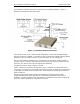
Figure 1-1 WLS Base Station Connections....................................................................................... 2
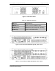
Figure 1-2 WLS Front Panel................................................................................................................3
Figure 1-3 Two Channel TDOA WLS (WLS2) - Rear Panel ..............................................................3
Figure 1-4 Four Channel TDOA WLS (WLS4) - Rear Panel .............................................................3
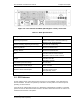
Figure 1-5 Four Channel AOA WLS (WLS4A) (Ext. switch) - Rear Panel.......................................4
Figure 1-6 GPS Antenna Splitter........................................................................................................5
Figure 1-7 RFDU with External Antenna Switch - Front View.........................................................6
Figure 1-8 RFDU with External Antenna Switch - Rear View ..........................................................6
Figure 1-9 Dual-Band RF Combiner – Rear View .............................................................................8
Figure 1-10 Dual-Band RF Combiner – Front View, Rack Mount....................................................9
Figure 1-11 Dual-Band RF Combiner - Wall Mount with WLS.........................................................9
Figure 2-1 Center Mount Bracket Configuration ............................................................................12
Figure 2-2 Front Mount Bracket Configuration ..............................................................................13
Figure 2-3 Wall Mount Bracket Configuration ................................................................................14
Figure 2-4 WLS/RFDU Power Connector Pin-out...........................................................................15
Figure 2-5 TDOA2 WLS Cabling Diagram .......................................................................................19
Figure 2-6 TDOA4 WLS Cabling Diagram .......................................................................................19
Figure 2-7 AOA Cabling Diagram for one AOA Panel....................................................................20
Figure 2-8 AOA Cabling Diagram for Multiple AOA Panels ..........................................................20
Figure 2-9 Mixed TDOA-AOA Multi Sector Cable Diagram............................................................21
Figure 2-10 Dual-band Combiner TDOA Cabling Diagram............................................................22
Figure 2-11 Noise Source, TDOA Site .............................................................................................26
Figure 2-12 Noise Source, AOA Site................................................................................................26
Figure 2-13 AOA Calibration Test....................................................................................................32
Figure 2-14 WLS Loopback Connector ...........................................................................................36
List of Tables
Table 1-1 WLS LED Indicators ...........................................................................................................3
Table 1-2 WLS Specifications ............................................................................................................4
Table 1-3 Cellular “A” RFDU Specifications.....................................................................................7
Table 1-4 Cellular “B” RFDU Specifications.....................................................................................7
Table 1-5 PCS RFDU Specifications..................................................................................................8
Table 1-6 Dual-Band Combiner Specifications ..............................................................................10
Table 2-1 WAN Cable Pin Assignment ............................................................................................16
Table 2-2 WLS Antenna Cabling ......................................................................................................18
Table 2-3 Description of Status Fields ............................................................................................30