
User's Manual


WLS Installation and Maintenance Manual Installation
Geometrix
®
Wireless Location System 34
Andrew Corporation Proprietary
Failure of the AOA calibration test most likely indicates faulty calibration cables or faulty antenna
cables. Failure could also indicate a fault in an antenna, RFDU, or antenna switch. It is unlikely
that failure would indicate a WLS fault, unless the Noise Correlation / Power test also indicates
failure. The Noise Correlation / Power test may also be used to localize problems in the RFDU or
antenna switch.
2.10.8 RF Cabling Test
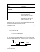
The RF Cabling Test detects the presence of an external amplifier, such as a multicoupler, prior
to the WLS. This test is used primarily to validate that the RF jumper cables between the
multicoupler and the WLS are physically installed, and that the multicoupler is actively amplifying.
This test does not verify the connection of antennas to the inputs of the multicoupler, nor does it
determine if the RF jumper cables are misconnected between channels or sectors. Also, in
release 5.3.7 and later, this test does not attempt to determine which RF bands are being filtered
within the multicoupler.
The test runs over multiple frequency bands, and does not require that there be active calls in the
bands being tested. Each properly cabled WLS port should pass each test regardless of band.
For example, if the WLS is connected to a cellular A-band multicoupler, the test will normally
indicate a pass condition for measurements in all RF bands, including cellular A, B, PCS, and
iDen. This is because thermal noise generated within the multicoupler broadband amplifier is not
affected by input band filtering. In the absence of any RF signal inputs to the multicoupler, the RF
spectrum output over all bands should be relatively uniform, with the level being determined by
the amplifier noise figure and gain.
Note: In this test, the signal levels shown are not true RSSI, or received signal strength
at the antenna, as it does not account for any gains prior to the WLS. It will only be an
accurate assessment of RSSI if the there is no external amplification applied during the test.
The RF Cabling Test determines that a cable is connected to the WLS if, averaging over all
bands:
• The minimum average signal level is greater than -109dBm, or
• The maximum average signal level is above -104dBm.
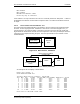
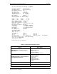
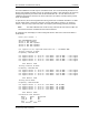
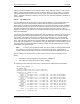
An example of a WLS with only antenna face 1 connected to a multicoupler is shown below:
Enter your choice: 8
RF CABLING TEST:
Checking average signal levels at WLS input ports ...
(Does not account for gains external to the WLS.)
Antenna Face 1 - Cabled for TDOA
Cellular A Band
Input: 1: Ave Signal Level: -112.9 dBm Max: -112.6 dBm (at 825.63 MHz)
Input: 5: Ave Signal Level: -113.5 dBm Max: -113.2 dBm (at 828.99 MHz)
Cellular B Band
Input: 1: Ave Signal Level: -113.4 dBm Max: -113.0 dBm (at 842.82 MHz)
Input: 5: Ave Signal Level: -113.7 dBm Max: -113.2 dBm (at 843.78 MHz)
PCS A Band
Input: 1: Ave Signal Level: -111.0 dBm Max: -110.5 dBm (at 1857.84 MHz)
Input: 5: Ave Signal Level: -111.6 dBm Max: -111.2 dBm (at 1857.84 MHz)
PCS B Band
Input: 1: Ave Signal Level: -112.4 dBm Max: -111.8 dBm (at 1870.62 MHz)
Input: 5: Ave Signal Level: -112.6 dBm Max: -112.1 dBm (at 1873.02 MHz)
IDEN Band
Input: 1: Ave Signal Level: -112.3 dBm Max: -111.8 dBm (at 810.31 MHz)
Input: 5: Ave Signal Level: -112.8 dBm Max: -112.3 dBm (at 810.91 MHz)
Antenna Face 2 - Cabled for TDOA
.
.