
Installation Guide
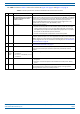
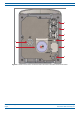
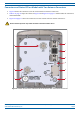
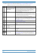
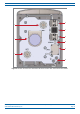
Table Of Contents
- Table of Contents
- Document Overview
- Era System Overview
- CAP H Overview
- Safely Working with a CAP H
- Installing a CAP H
- Using the Status LED to Determine State of the CAP H
- Maintenance
- Contacting CommScope

M0201AKD_uc CommScope Era
™
High Power Carrier Access Point Installation Guide
© December 2019 CommScope, Inc. Page 7
CAP H Overview
The “REF#” column in Table 2 refers to the callouts in Figure 2 on page 6 and Figure 3 on page 8.
Table 2. Function of Connectors and Status LED Models with One Antenna Connector
REF # Label Description Function
1 A RJ45 Auxiliary port
(Not supported by current software,
but will be
supported in a future
software version.)
Connects to external Ethernet devices such as WiFi and IP cameras. Cabling is via the
appropriate CAT cable for the protocol; this model supports a 1000 BASE-T and 802.3at
Class 4 Power over Cat6A Ethernet connection. Maximum attached cable length is 3
meters (9.8 feet), per 802.3ATclass4 standards. The Auxiliary port ships with
factory-installed EMI/weatherproof plug and must remain plugged if not in use;
graphic shows an OCTIS connector (PN 7760652) in black.
2 1 Optical Port 1 Can be one of the following:
• Connects to a Primary CAP H to a Classic CAN or TEN to provide the
main signal
interface. Optical transport occurs over Single Mode Fiber (SMF) or Multi Mode
Fiber (MMF). Requires Optical OCTIS Kit (PN 7770612); Optical Port 1 ships with a
dust cap that can be discarded upon unit installation.
• Connects a Secondary CAP H to Optical Port 2 of the Primary CAP H.
3 2 Optical Port 2 Connects to an optional cascaded secondary CAP H via an Optical OCTIS Kit (PN
777061
2). Optical transport occurs over Single Mode Fiber (SMF) or Multi Mode Fiber
(MMF). Optical Port 2 ships with factory-installed EMI/weatherproof plug, and must
remain plugged if not in use. For information on cascading APs, see "CAP H Installation
and Cascade Rules" on page 20.
4 STATUS Status LED Provides a visual indication of the status of the CAP H; see "Using the Status LED to
Determine State of the CAP H" on page 47.
5 LOCAL Micro USB network port Provides a local connection to a laptop. This port is not required for normal operation
of th
e unit and should only be used when requested by CommScope Technical
Support.
6
• AC version—One M8 bolt, hex nut,
and washers
• DC version—Two M6 bolt, hex nut,
and washers
Provides earth ground for the CAP H chassis.
7 MAINS Power connector • AC version—Provides the power to CAP H models that use standard AC (100 to 240
Vac) power
.
• DC version—Provides the power to CAP H models that use DC (-60 to -48 Vdc)
power.
8 ANT 4.3-10 RF connector Transmits and receives signals to and from d
istributed antennas. This RF port can be
connected directly to an antenna (using RF jumper cables) or through splitters,
allowing additional antennas to be fed by the CAP H.