CommScope Era™ High Power Carrier Access Point Installation Guide • M0201AKC • April 2019
DISCLAIMER This document has been developed by CommScope, and is intended for the use of its customers and customer support personnel. The information in this document is subject to change without notice. While every effort has been made to eliminate errors, CommScope disclaims liability for any difficulties arising from the interpretation of the information contained herein.
TABLE OF CONTENTS Document Overview .................................................................................................................................................................................. 1 Document Revision History .............................................................................................................................................................................. 1 Document Cautions and Notes.................................................................
Table of Contents Contacting CommScope ........................................................................................................................................................................... 53 CMS Global Technical Support ....................................................................................................................................................................... 53 Telephone Helplines...............................................................................
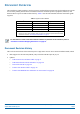
D OCUMENT O VERVIEW This installation guide provides a product overview and installation instructions for the High Power Carrier Access Point (CAP H), which allows transmission between CommScope Era™ equipment, antennas, and Ethernet devices (such as WiFi and IP cameras). Table 1 lists the CAP H models that this installation guide supports. Table 1.
Document Overview Document Cautions and Notes This document may contain any of the following notes, cautions and warning icons. The icon to the left is used to indicate a caution or warning. Cautions and warnings indicate operations or steps that could cause personal injury, induce a safety problem in a managed device, destroy or corrupt information, or interrupt or stop services. The icon to the left indicates a caution or warning that pertains to laser equipment.
Document Overview Abbreviations Used in this Guide AC Alternating Current ISDE Innovation, Sciences et Développement économique Canada AUX Auxiliary ISED Innovation, Science and Economic Development Canada C Celsius kg Kilogram CAN Central Area Node LED Light Emitting Diode CAP H Carrier Access Point, High Power MHz Megahertz CAP L MIMO Multiple Input Multiple Output CAP M Carrier Access Point, Medium Power mm Millimeter Cat Category MMF Multi-Mode Fiber CAT Copper Transport
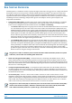
Era System Overview E RA S YSTEM O VERVIEW CommScope Era™ coordinates wireless capacity throughout the entire coverage area via a single centralized head-end location or from an operator’s existing C-RAN hub. Based on ION-E®, Era operates on the same cost-efficient standard IT cabling as ION-E and is compatible with ION-E deployments.
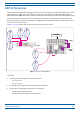
CAP H Overview CAP H O VERVIEW This installation guide describes the High Power Carrier Access Point (CAP H), which interfaces with a Classic CAN or TEN via an optical link. This allows the CAP H to provide data over Single-Mode Fiber (SMF), or Multi-Mode Fiber (MMF). Power for a CAP H is provided over internal AC/DC (AC version) or DC (DC version). On the downlink, the CAP H converts data arriving at the CAP H to analog signals and sends them to the Antenna port.
CAP H Overview CAP H Connectors and Status LED The CAP H connectors and Status LED are described in the following sections: • "Connectors and Status LED on Models with One Antenna" on page 6 • "Connectors and Status LED on Models with Two Antenna Connectors" on page 9. Connectors and Status LED on Models with One Antenna • Figure 2 shows the connectors on an AC version of the CAP H that has one antenna connector.
CAP H Overview The “REF #” column in Table 2 refers to the callouts in Figure 2 on page 6 and Figure 3 on page 8. Table 2. Function of Connectors and Status LED Models with One Antenna Connector REF # Label Description Function 1 A RJ45 Auxiliary port Connects to external Ethernet devices such as WiFi and IP cameras. Cabling is via the appropriate CAT cable for the protocol; this model supports a 1000 BASE-T and 802.3at Class 4 Power over Cat6A Ethernet connection.
CAP H Overview 1 2 3 4 8 7 5 6 Figure 3. Location of Connectors and Status LED on DC Version with One Antenna Connector CommScope Era™ High Power Carrier Access Point Installation Guide Page 8 M0201AKC © April 2019 CommScope, Inc.
CAP H Overview Connectors and Status LED on Models with Two Antenna Connectors • Figure 4 shows the connectors on an AC version with two antenna connectors. • Table 3 on page 10 maps the callouts in Figure 4 and Figure 5 on page 11 and describes the connectors and STATUS LED. • Figure 5 on page 11 shows the connectors on a DC version with two antenna connectors. Do not remove caps from any of the connectors until instructed to do so. 1 9 2 3 4 8 7 5 6 Figure 4.
CAP H Overview The “REF #” column in Table 2 refers to the callouts in Figure 2 on page 6 and Figure 5 on page 11. Table 3. Function of the Connectors and Status LED Models with Two Antenna Connectors REF # Label Description Function 1 A RJ45 Auxiliary port Connects to external Ethernet devices such as WiFi and IP cameras. Cabling is via the appropriate CAT cable for the protocol; this model supports a 1000 BASE-T and 802.3at Class 4 Power over Cat6A Ethernet connection.
CAP H Overview 1 9 2 3 7 4 5 8 6 Figure 5. Location of Connectors and Status LED on DC Version with Two Antenna Connectors M0201AKC © April 2019 CommScope, Inc.
CAP H Overview CAP H Accessory Options The following sections describe hardware options for the CAP H. Mounting Kits You must order one of following mounting kits, as appropriate for this installation. The mounting kit must be ordered separately; it is not contained with the standard equipment. • • Wall Mounting Kit (CommScope Part Number 7661581), includes the following: – One Top Mounting Bracket – One Bottom Mounting Bracket – Four M8x25 screws – Four split-lock washers – Four 8.
CAP H Overview OCTIS Kits All CAP H units include one OCTIS1 Kit for the primary interface to a Classic CAN or TEN that CAP H plugs into the CAP H Optical Port 1. You can order an additional OCTIS Kit, which would allow you to cascade two CAP Hs via Optical Port 2, or to attach an auxiliary Ethernet device via the AUX Port. Table 4 identifies the OCTIS Kit options. CAP H cascading using Optical Port 2 is not supported by the current software version but is planned for a future software version.
Safely Working with a CAP H S AFELY W ORKING WITH A CAP H The following sections provide important information that you should read and know before working with the CAP H. Observe all cautions and warnings listed in this section and elsewhere in this installation guide. RF Safety Cautions This system is a RF Transmitter and continuously emits RF energy. Maintain a minimum clearance from the antenna as specified in Table 6 while the system is operating.
Safely Working with a CAP H Property Damage Warnings Only suitably qualified personnel are allowed to work on this unit and only after becoming familiar with all safety notices, installation, operation and maintenance procedures contained in this installation guide. Keep operating instructions within easy reach and make them available to all users. Only license holders for the respective frequency range are allowed to operate this unit.
Safely Working with a CAP H General Installation Safety Requirements Wet conditions increase the potential for receiving an electrical shock when installing or using electrically powered equipment. To prevent electrical shock, never install or use electrical equipment in a wet location or during a lightning storm. Do not remove caps from any of the connectors until instructed to do so. Read and observe all the warning labels attached to the unit.
Safely Working with a CAP H 4 Notice: For installations which have to comply with FCC/ISED requirements: English: This device complies with FCC Part 15. Operation is subject to the following two conditions: (1) this device may not cause interference, and (2) this device must accept any interference, including interference that may cause undesired operation of the device. This device complies with Health Canada's Safety Code.
Safely Working with a CAP H 6 Notice: Corresponding local particularities and regulations must be observed. For national deviations, please refer to the respective documents included in the manual CD that is delivered with the unit. 7 Note: For a Class B digital device or peripheral: This equipment has been tested and found to comply with the limits for a Class B digital device, pursuant to part 15 of the FCC Rules.
Safely Working with a CAP H Equipment Symbols Used / Compliance Please observe the meanings of the following symbols used in our equipment and the compliance warnings listed in Table 5. Table 5. Compliance Labels Symbol Compliance Meaning For industrial (Part 20) signal booster: WARNING: This is NOT a CONSUMER device. It is designed for installation by FCC LICENSEES and QUALIFIED INSTALLERS. You MUST have an FCC LICENSE or express consent of an FCC Licensee to operate this device.
Installing a CAP H I NSTALLING A CAP H The following sections guide you through the installation of a CAP H. Pay attention to all cautions and follow the steps in the order presented. CAP H Installation and Cascade Rules Support for cascading of CAP H APs is not currently supported. This feature is planned for Era Software V2.7 and above. • • When installing a CAP H, you must observe the following rules. – The CAP H connects via its Optical Port 1 to an OPT Card in a Classic CAN or TEN.
Installing a CAP H Recommended Tools and Material • Electrostatic Discharge (ESD) wrist strap • Drill and bits that can penetrate the selected mounting surface • 13mm wrench, used for wall or pole mounting the CAP H • One of two mounting kits, which is ordered separately (see "CAP H Accessory Options" on page 12) • Earth-bonding cable to ground the CAP H chassis • Fiber cleaning equipment: Isopropyl alcohol, compressed air, lint-free wipe, and cotton buds.
Installing a CAP H If any different or additional mounting material is used, ensure that the mounting remains as safe as the mounting designed by the manufacturer. The specifications for stationary use of the CAP H must not be exceeded. Ensure that the static and dynamic strengths are adequate for the environmental conditions of the site. The mounting itself must not vibrate, swing or move in any way that might cause damage to the CAP H. A spacing of 50 mm (1.97 inch) around the unit is required.
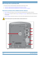
Installing a CAP H Determine the Mounting Site When deciding on a suitable mounting site, observe the following rules. • The CAP H is suitable for installation indoors or outdoors. • Use the weights listed in Table 7 to determine a site that can bear the weight of the CAP H that is being installed, where: – The “Maximum Lift Weight” is the highest weight that must be lifted during installation. (An installer should lift the CAP H components one at a time, not a wholly configured CAP H.
Installing a CAP H 18 16 21 20 17 19 17 15 14 6 9 4 2 5 12 10 3 11 13 7 1 8 Figure 6. Required Space to Mount a CAP H CommScope Era™ High Power Carrier Access Point Installation Guide Page 24 M0201AKC © April 2019 CommScope, Inc.
Installing a CAP H Wall Mounting a CAP H This procedure tells you how to mount the CAP H to a wall using the Wall Mounting Kit (CommScope Part Number 7661581). It is the responsibility of the installer to verify that the supporting surface will safely support the combined load of the electronic equipment and all attached hardware and components and to ensure that the CAP H is safely and securely mounted. 1 Mark the position of the drilling holes.
Installing a CAP H 2 Drill four holes (two holes per bracket) at the positions marked in Step 1. 3 Insert anchors in each of the holes drilled in Step 2. The anchors are not included with the CAP H shipment as the suitable type depends on the wall material). Anchors should be used for all wall mountings, except for when mounting to a wooden wall.
Installing a CAP H 5 Do the following to mount the CAP H in the Wall Mount Bracket. a Hang the CAP H in the upper bracket. b Push the CAP H into to the lower bracket (A), and then fasten it to the lower bracket using two M8x20 screws (B), split-lock washers (C) and flat washers (D) so that the flat washers are against the mounting bracket; torque to 27 N-m. A B C D M0201AKC © April 2019 CommScope, Inc.
Installing a CAP H Pole Mounting a CAP H This procedure tells you how to mount the CAP H to a wall using the Pole Mounting Kit (CommScope Part Number 7661538). It is the responsibility of the installer to verify that the pole will safely support the combined load of the electronic equipment and all attached hardware and components and to ensure that the CAP H is safely and securely mounted. The maximum diameter of the pole or column cannot exceed 120 mm (4.7 inch). f um o Maxim (4.
Installing a CAP H 1 Mark the position of where the screw bands should be attached to the pole, as shown in the following graphic, which also shows the pole-mounting pitches. Minimum: 775 mm (30.51”) Maximum 788 mm (31”) M0201AKC © April 2019 CommScope, Inc.
Installing a CAP H 2 Use two screw bands (B) for the upper and one for the lower bracket to fasten the two brackets (A) to the pole, as shown below. A B CommScope Era™ High Power Carrier Access Point Installation Guide Page 30 M0201AKC © April 2019 CommScope, Inc.
Installing a CAP H 3 Place the bands around the pole or post and feed the loose end into the lock and tighten the slotted screw securely. When the screw is turned clockwise, it acts as a worm drive and pulls the threads of the band, causing the band to tighten around the pole. When fastening the brackets, make sure that they are installed congruently and not at an angle to each other. To determine the distance between the clamps, refer to Step 1 on page 29.
Installing a CAP H Install the CAP H Cables The following sections tell you how to cable the CAP H. Follow the procedures in the order in which they are given. Ground the CAP H The CAP H must be grounded. Do not use the grounding bolts to connect an external device. 1 Connect an earth-bonding cable to the grounding bolt connections on the outside of the CAP H chassis, as shown in the graphic to the right. • AC versions will have one M8 bolt; see Figure 2 on page 6.
Installing a CAP H 2 Connect the earth-bonding cable as shown in the graphic to the right. a Loosen the hex nut, and then connect the earth-bonding cable between the two washers. b Refasten all parts by tightening the hex nut. c Connect the other end of the earth-bonding cable to a suitable permanent ground.
Installing a CAP H Connect the Antenna Cable The following information regarding antenna mapping and is relevant to all CAP H variants. • For Non-MIMO bands, there is no channel mapping option for the transceiver/antenna port. The transceiver/antenna port relationship is fixed in hardware. • For MIMO bands, the Era GUI maps MIMO channels according to their AP designation: – AP0 to antenna port ANT1 – AP1 to antenna port ANT2.
Installing a CAP H Clean the RF Cable Connectors This section tells you how to clean RF cable connectors. The graphics in this section illustrate the cleaning procedure and do not show the CAP H. This procedure requires the use of compressed air. Wear protective clothing—especially protective glasses—to protect against injury from flying particles. This procedure requires the use of flammable material. There is a risk of fire. Keep away from sources of ignition.
Installing a CAP H 4 Use a lint-free wipe drenched with isopropyl alcohol to clean the connector winding. 5 Use a cotton bud drenched with isopropyl alcohol to clean the lip of the inner ring. 6 Use a cotton bud drenched with isopropyl alcohol to clean the inside surface of the inner ring. 7 Use a cotton bud drenched with isopropyl alcohol to clean the inside of the center conductor spring tines.
Installing a CAP H 9 Use compressed air to remove metal chips and small particles from the mating and inner surfaces of the connector. 10 Use a lint-free wipe drenched with isopropyl alcohol to clean the winding area. 11 Use a cotton bud drenched with isopropyl alcohol to clean the inside mating surface of the inner ring. 12 Use a cotton bud drenched with isopropyl alcohol to clean the outside surface of the center pin.
Installing a CAP H 2 Join the connectors and turn the coupling nut until the thread grips. 3 Push in the connector until it clicks. 4 Fasten the coupling nut hand-tight. Do not turn the connector but the coupling nut only. 5 Retain the cable connector with the counter wrench (A) and fasten the coupling nut with the torque wrench (B) until the torque is applied (torque wrench clicks).
Installing a CAP H Connect the Optical Fiber 1 Contact your local CommScope sales representative to obtain the following components, as required, for this installation. • Per the installation plan, obtain either Single Mode Fiber (SMF) or Multi Mode Fiber (MMF) that is of sufficient length to reach from the CAP H to a Classic CAN or TEN. • All CAP Hs ship with the required Optical OCTIS Kit (PN 7770612). If cascading a Secondary CAP H, a second Optical OCTIS Kit is required.
Installing a CAP H 2 3 Connect the CAP H Optical Port 1 as appropriate for this installation. Note the maximum range listed in Table 10. See "CAP H Connectors and Status LED" on page 6 for the location of Optical Port 1. a Remove the dust cap from the CAP H Optical Port 1 connector and the connectors on the SMF or MMF. b Follow the local cleaning technique to clean Optical Port 1. c Clean the connectors on the SMF or MMF following the fiber supplier’s recommendations.
Installing a CAP H Connect the MAINS Power This section tells you how to connect the mains power to the CAP H. Read and observe all cautions and follow the steps in the order in which they are presented. Working Safely with MAINS Power Read and observe all cautions listed in "Safely Working with a CAP H" on page 14. Electrical hazard. Danger of death or fatal injury from electrical current.
Installing a CAP H Connect the MAINS Power and Power on an AC CAP H This section provides information for powering an AC CAP H. If you are installing a DC CAP H, go to "Connect the MAINS Power and Power on a DC CAP H" on page 44. A MAINS Power cable for AC ships with each CAP H; see Figure 7. Note that there are two MAINS Power cables, make sure you are referring to the specifications for the cable with which you are working. Outer diameter of cable is 8.9mm 3x1.5mm2 3.2 m 10.
Installing a CAP H Do the following to connect the MAINS power to the CAP H. 1 Follow the steps in "Ground the CAP H" on page 32. 2 Locate the MAINS power cable that was delivered with the CAP H (shown in Figure 7 on page 42). 3 Locate or install a suitable power junction box or receptacle near the CAP H, and then route the power cable from the power source to the CAP H. Do not connect the cable to the CAP H MAINS connector at this time. The power source must be interruptible.
Installing a CAP H Connect the MAINS Power and Power on a DC CAP H This section provides information for powering a DC CAP H. If you are installing an AC CAP H, go to "Connect the MAINS Power and Power on an AC CAP H" on page 42. The MAINS cable must be properly secured observing local regulations and electrical codes. Be sure to allow enough slack in the cable at the CAP H to mount or dismount the cable into the DC MAINS connector of the CAP H.
Installing a CAP H Do the following to connect the CAP H MAINS power connector to DC power. Danger of electrical hazard by high current. Disconnect MAINS power before opening the DC connector housing in Step 1 below. 1 Unscrew the two M3 x 12 captive screws and take off the cover from the DC MAINS connector housing. At the CAP H housing, the cover is inserted into a recess, so first lift the cover at the front and carefully pull it out from the recess. 2 Remove the rubber plug.
Installing a CAP H 4 Insert the wiring through the opening and mount it to the M6 MAINS terminals, as shown in the following graphic. • Observe the correct polarity. • Close the conduit fitting to ensure water tightness. • For strain release, two M5 threaded holes are provided; the distance between the threaded holes is 34.5 mm (1.36”). - + B D A A 5 mm (.2”) B 34.5 mm (1.36”) C O 34.52 mm (1.36”) C 5 D 8 mm (.
Using the Status LED to Determine State of the CAP H U SING THE S TATUS LED TO D ETERMINE S TATE OF THE CAP H You use the Status LED, which is on the bottom of the CAP H on its Connector panel (see "CAP H Connectors and Status LED" on page 6) to determine the current operational state of the CAP H. The color of the Status LED indicates the state of the CAP H, as described below. • Off—The CAP H is not powered on, check for a MAINS power failure.
Maintenance M AINTENANCE Maintenance of the CAP H and replacement of components should only be performed as described in this section. For most maintenance procedures, appropriate tools are required to ensure correct handling. All of these tools can be ordered from the supplier. Unless otherwise agreed to in writing by CommScope, CommScope's general limited product warranty (http://www.commscope.
Maintenance Routine Maintenance of the CAP H Check the cleanliness of the CAP H—in particular its heat sink / fan(s)—at appropriate intervals depending on the degree of dust and dirt at the installation site. If necessary, any dusty or dirty areas / parts should be cleaned at regular intervals, which is also dependent on the degree of dust and dirt at the installation site. Replacing the Fan Unit Replacement of the Fan Unit is not required as a preventative measure.
Maintenance 4 Unscrew the four Pan-head screws (two at each side of the cabinet): Pan-Head screws (two each side of the chassis) 5 Remove the fan cover. CommScope Era™ High Power Carrier Access Point Installation Guide Page 50 M0201AKC © April 2019 CommScope, Inc.
Maintenance 6 Do the following to remove the Fan Unit: a Unscrew and disconnect the fan connector. b Unscrew the four Pan-head screws that secure the fan plate to the CAP H chassis. c Pull the Fan Unit from the CAP H chassis. Pan-Head screw Pan-Head screw Pan-Head screw Pan-Head screw Fan connector 7 8 Do the following to install the new Fan Unit: a Insert the new Fan Unit into the CAP H chassis.
Maintenance Cleaning the Heat Sink This procedure requires the use of compressed air. Risk of injury by flying particles when compressed air is used. Wear protective clothing, especially protective glasses. Rotating fans. Risk of injury in operation. Wear tight-fitting clothes and disconnect mains before connecting or replacing or cleaning the Fan Unit. All CAP H screws have a right-hand thread. Use an appropriate tool to tighten or loosen them.
Contacting CommScope C ONTACTING C OMM S COPE The following sections tell you how to contact CommScope for additional information or for assistance. CMS Global Technical Support The following sections tell you how to contact the CommScope Mobility Solutions (CMS) Technical Support team. Support is available 7 days a week, 24 hours a day. Telephone Helplines Use the following Helpline telephone numbers to get live support, 24 hours a day: 24x7 +1 888-297-6433 (Toll free for U.S.
Contacting CommScope Hardware to Software Mapping Information 1 Scan the QR Code to the right to view or download the minimum software requirements for each of the DCCS hardware modules. Alternatively, you can go to the following web address to access the portal: http://www.commscope.com/collateral/DCCS_HW_SW_Mapping/ 2 Click on a document link to open it, or right click on the link and select the Save target as… option from the contextual menu.
Contacting CommScope Accessing Era/ION-E Series User Documentation 1 Scan the QR Code to the right to go directly to the CommScope DCCS Customer Portal, where you can access the DCCS user documentation. Alternatively, you can go to the following web address to access the portal: https://www.mycommscope.com 2 Access to the Customer Portal requires a user account and password.