
Installation Guide
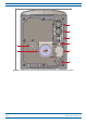
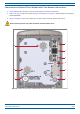
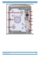
Table Of Contents
- Table of Contents
- Document Overview
- Era System Overview
- CAP H Overview
- Safely Working with a CAP H
- Installing a CAP H
- Using the Status LED to Determine State of the CAP H
- Maintenance
- Contacting CommScope

CommScope Era
™
High Power Carrier Access Point Installation Guide M0201AKC
Page 10 © April 2019 CommScope, Inc.
CAP H Overview
The “REF #” column in Table 2 refers to the callouts in Figure 2 on page 6 and Figure 5 on page 11.
Table 3. Function of the Connectors and Status LED Models with Two Antenna Connectors
REF # Label Description Function
1 A RJ45 Auxiliary port Connects to external Ethe
rnet devices such as WiFi and IP cameras. Cabling is via the
appropriate CAT cable for the protocol; this model supports a 1000 BASE-T and 802.3at
Class 4 Power over Cat6A Ethernet connection. Maximum attached cable length is 3
meters (9.8 feet), per 802.3ATclass4 standards. For information on the Auxiliary port
in cascades, see "CAP H Installation and Cascade Rules" on page 20. The Auxiliary port
ships
with factory-installed EMI/weatherproof plug, and must remain plugged if not in
use; graphic shows an OCTIS connector (PN 7760652) in black.
2 1 Optical Port 1 Can be one of the following:
• Connects to a Primary CAP H to a Classic CAN or TEN to provide
the main signal
interface. Optical transport occurs over Single Mode Fiber (SMF) or Multi Mode
Fiber (MMF). Requires Optical OCTIS Kit (PN 7770612); Optical Port 1 ships with a
dust cap that can be discarded upon unit installation.
• Connects a Secondary CAP H to Optical Port 2 of the Primary CAP H.
3 2 Optical Port 2
(Not supported by current software,
but
will be supported in a future
software version.)
Connects to an optional cascaded secondary CAP H via an Optical OCT
IS Kit (PN
7770612). Optical transport occurs over Single Mode Fiber (SMF) or Multi Mode Fiber
(MMF). Optical Port 2 ships with factory-installed EMI/weatherproof plug, and must
remain plugged if not in use.
4 STATUS Status LED Provides a visual indication of the status of the CAP H; see "Using the Status LED to
Determine State of the CAP H" on page 47.
5 LOCAL Mini USB network port Provides a local connection to a laptop. This port is not require
d for normal operation
of the unit, and should only be used when requested by CommScope Technical
Support.
6
• AC version—One M8 bolt, hex nut,
and washers
• DC version—Two M6 bolt, hex nut,
and washers
Provides earth ground for the CAP H chassis.
7 MAINS Power connector • AC version—Provides the power to CAP H models that use standard AC (100 to 240
Vac) power
.
• DC version—Provides the power to CAP H models that use DC (-60 to -48 Vdc)
power.
8 ANT2
4.3-10 RF connector
Connect to two separate external
antennas or to two ports on a cross-polarized dual
antenna via 50 coaxial cable. Each connector supp
orts two RF bands; see "Connect
the Antenna Cable" on page 34. These RF ports can be connected directly to an
an
tenna (using RF jumper cables) or through splitters, allowing additional antennas to
be fed by the CAP H.
9 ANT1