
Installation Guide
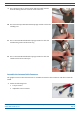
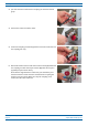
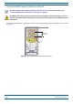
Table Of Contents
- Table of Contents
- Document Overview
- Era System Overview
- CAP H Overview
- Safely Working with a CAP H
- Installing a CAP H
- Using the Status LED to Determine State of the CAP H
- Maintenance
- Contacting CommScope

CommScope Era
™
High Power Carrier Access Point Installation Guide M0201AKC
Page 46 © April 2019 CommScope, Inc.
Installing a CAP H
4 Insert the wiring through the opening and mount it to the M6 MAINS terminals, as shown in the following
graphic.
• O
bserve the correct polarity.
• C
lose the conduit fitting to ensure water tightness.
• F
or strain release, two M5 threaded holes are provided; the distance between the threaded holes is
34.5 mm (1.36”).
A
B
C
D
5 mm (.2”)
A
34.5 mm (1.36”)
B
8 mm (.32”)
D
C
34.52 mm (1.36”)
O
+
-
5 Mount the housing cover by inserting it into the recess at the repeater cabinet and fastening the two
M3 x 12 captive screws.
MAINS power must be interruptible with an external mains breaker (40 A). For the MAINS breaker,
observe the local regulations of the DC provider.
Do not connect or disconnect the power cord at the MAINS connector while power is on. Turn off MAINS
power before connecting the power cord at the CAP H, then, engage MAINS again.