Installation Guide
Manuals
Brands
Andrew Wireless System Manuals
Electronics
ERA Repeater for cellular systems
11
12
13
14
15
16
17
18
19
20
Table Of Contents
Table of Contents
Document Overview
Document Revision History
Document Cautions and Notes
Abbreviations Used in this Guide
ERA System Overview
CAP H Overview
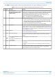
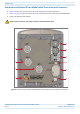
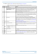
CAP H Connectors and Status LED
Connectors and Status LED on Models with One Antenna
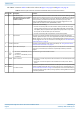
Connectors and Status LED on Models with Two Antenna Connectors
Connectors and Status LED on Models with Three Antenna Connectors
CAP H Accessory Options
Mounting Kits
OCTIS™ Kits
OCTIS Kit Instructions
OCTIS SFP+ Reverse Lever Assembly Instructions
Safely Working with a CAP H
RF Safety Cautions
Health and Safety Precautions
Property Damage Warnings
Guard Against Damage from Electro-Static Discharge
General Installation Safety Requirements
Compliance
Equipment Symbols Used / Compliance
Required Antenna Distances
Maximum Output Power Levels
Installing a CAP H
CAP H Installation and Cascade Rules
Prepare for Installation
Recommended Tools and Material
Unpack and Inspect the CAP H and Optional Accessories
Installation Cautions
Determine the Mounting Site
Wall Mounting a CAP H
Pole Mounting a CAP H
Install the CAP H Cables
Ground the CAP H
Connect the Antenna Cable
Clean the RF Cable Connectors
Assemble the Antenna Cable Connector
Connect the Optical Fiber
Connect an Auxiliary Device
Connect the MAINS Power
Working Safely with MAINS Power
Connect the MAINS Power and Power on an AC CAP H
Connect the MAINS Power and Power on a DC CAP H
Using the Status LED to Determine State of the CAP H
Maintenance
Rules to Observe During Maintenance
Routine Maintenance of the CAP H
Replacing the Fan Unit
Cleaning the Heat Sink
Contacting CommScope
CMS Global Technical Support
Telephone Helplines
Online Support
Waste Electrical and Electronic Equipment Recycling
Hardware to Software Mapping Information
Technical Training
Accessing ERA Series User Documentation
CommScope ERA
®
High Power Carrier Access Point Installation Guide
M0201AKG_uc
Page 8
© Fe
bruary 2021 CommScope, Inc.
CAP
H Overview
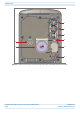
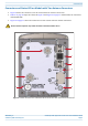
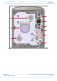
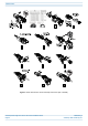
Figure 3.
Location of Connectors and Status LED on D
C Version with One Antenna Connector
1
2
3
6
5
7
8
4
1
...
...
10
11
12
13
14
...
...
66