
Installation Guide


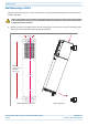

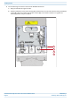


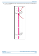
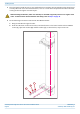
Table Of Contents
- Table of Contents
- Document Overview
- ERA System Overview
- CAP H Overview
- Safely Working with a CAP H
- Installing a CAP H
- Using the Status LED to Determine State of the CAP H
- Maintenance
- Contacting CommScope

M0201AKG_uc CommScope ERA
®
High Power Carrier Access Point Installation Guide
© February 2021 CommScope, Inc. Page 27
Installing a CAP H
If any different or additional mounting material is used, ensure that the mounting remains as safe as the
mounting designed by the manufacturer. The specifications for stationary use of the CAP H must not be
exceeded. Ensure that the static and dynamic strengths are adequate for the environmental conditions of
the site. The mounting itself must not vibrate, swing or move in any way that might cause damage to the
CAP H.
A spacing of 50 mm (1.97 inch) around the unit is required.
To ensure sufficient airflow when mounting the CAP H in enclosed spaces, two lid openings (one for the
air inlet and the other for the air outlet) must be provided. Do not block these air inlets and outlets when
mounting the CAP H. The size of each opening must equal at least 18 x 18 cm (> 300 cm2). Ensure that
there is no thermal short circuit between the air inlet and air outlet. Make sure free airflow is not
deflected or otherwise obstructed.
Observe all additional rules or restrictions regarding mounting that apply to specific CAP H types. For
details refer to the mechanical specifications in the data sheet for the unit. Install the unit vertically with
the Fan Unit at the top. A maximum tilt angle of 25° from a vertical position must be maintained, as shown
in the following illustration.