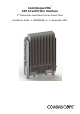
CommScope ERA® CAP L2 with Fiber Interface 2nd Generation Low Power Carrier Access Point Installation Guide • M0203A9B_uc • September 2022
DISCLAIMER This document has been developed by CommScope, and is intended for the use of its customers and customer support personnel. The information in this document is subject to change without notice. While every effort has been made to eliminate errors, CommScope disclaims liability for any difficulties arising from the interpretation of the information contained herein.
TABLE OF CONTENTS Document Overview .................................................................................................................................................................................. 1 Document Revision History .............................................................................................................................................................................. 1 Document Cautions and Notes.................................................................
Table of Contents Accessing ERA Series User Documentation .................................................................................................................................................... 47 CommScope ERA® CAP L2 with Fiber Interface Page iv M0203A9B_uc © September 2022 CommScope, Inc.
D OCUMENT O VERVIEW CAP L2 variants are available with either a copper entry module or fiber entry module. The "C" in the variant name (after the band numbers) indicates a copper entry module and an "F" indicates a fiber entry module. The copper entry module supports up to two 10GBase-T (CAT6A) interfaces and the fiber entry module supports up to two 10G/25G SFP+ optical fiber interfaces. This guide provides a product overview and installation instructions for the fiber CAP L2 APs.
Document Overview The icon to the left indicates a caution or warning that pertains to Radio Frequency (RF). The icon to the left indicates that the hardware is susceptible to Electro-Static Discharge (ESD) damage. The icon to the left indicates a caution or warning that pertains to an electrical hazard. The icon to the left indicates a Note. Notes provide information about special circumstances. CommScope ERA® CAP L2 with Fiber Interface Page 2 M0203A9B_uc © September 2022 CommScope, Inc.
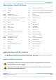
Document Overview Abbreviations Used in this Guide AP Access Point EFTA European Free Trade Association AUX Auxiliary ISDE Innovation, Sciences et Développement économique Canada C Celsius ISED Innovation, Science and Economic Development Canada CAN Central Area Node kg Kilogram CAP L Low Power Carrier Access Point LED Light Emitting Diode CAP L2 Low Power Carrier Access Point, Second Generation LPS Limited Power Source CAP M Medium Power Carrier Access Point MHz Megahertz Cat
Document Overview High frequency radiation in operation. Risk of health hazards associated with radiation from the antenna(s) connected to the unit. Implement prevention measures to avoid the possibility of close proximity to the antenna(s) while in operation. If the CAP L2 power connector is not easily accessible, a disconnect device in the mains power circuit must be provided within easy reach. Property Damage Warnings Keep operating instructions within easy reach and make them available to all users.
Document Overview Compliance 1 Notice: For installations, which have to comply with FCC RF exposure requirements, the antenna selection and installation must be completed in a way to ensure compliance with those FCC requirements.
Document Overview transmitter. Users and installers must be provided with antenna installation instructions and transmitter operating conditions for satisfying RF exposure compliance. French: Cet appareil est conforme avec Santé Canada Code de sécurité 6. Le programme d'installation de cet appareil doit s'assurer que les rayonnements RF n'est pas émis au-delà de I'exigence de Santé Canada. Les informations peuvent être obtenues: http://www.hc-sc.gc.ca/ewh-semt/pubs/radiation/radio_guide-lignes_direct-eng.
Document Overview • • • • 8 9 Reorient or relocate the receiving antenna. Increase the separation between the equipment and receiver. Connect the equipment into an outlet on a circuit different from that to which the receiver is connected. Consult the dealer or an experienced RF technician for help. Notice: For a Class A digital device or peripheral. This equipment has been tested and found to comply with the limits for a Class A digital device, pursuant to Part 15 of the FCC Rules.
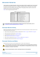
Document Overview Maximum Output Power Levels Table 3 lists the frequencies and maximum power output for bands supported in the CAP L2 variants. Table 3. Maximum Power Output by Frequency Band Radio Module Number DL Frequency Range Power Output [dBm] 6 Radio Module L2 B71 619.5 - 649.5 MHz 19 Radio Module L2 B12 +13+14 731.5 - 753.5 748.5 - 753.5 MHz 760.5 - 765.
Fiber CAP L2 Overview F IBER CAP L2 O VERVIEW This installation guide describes the Fiber CAP L2, which interfaces with a Classic CAN or TEN via an optical link. This allows the Fiber CAP L2 to provide data over Single-Mode Fiber (SMF) or Multi-Mode Fiber (MMF). Power for Fiber CAP L2s is provided over External AC/DC or remotely through hybrid fiber. On the downlink, the Fiber CAP L2 converts data arriving at the CAP L2 to analog signals and sends them to the Antenna ports.
Fiber CAP L2 Overview Table 5. Function of the CAP L2 Connectors and LED (2 antennas) (Continued) Ref # Label Description Function 3 None Proprietary 4-pin DC power connector Connects to a local or remote DC power supply. The CAP L2 does not ship with any power cables preinstalled; you need to order the power cable assembly that is appropriate for this installation. • 7774061: Cable Assembly, CAP L Local Power Jumper, 0.5 m • 7816237-xx: Cable Assembly, CAP L Local Power Jumper, 3.0 m 4 ANT 2 4.
Fiber CAP L2 Overview Table 6. Function of the CAP L2 Connectors and LED (4 antennas) (Continued) Ref # Label Description Function None Proprietary 4-pin DC power connector Connects to a local or remote DC power supply. The CAP L2 does not ship with any power cables preinstalled; you need to order the power cable assembly that is appropriate for this installation. 4 • 7774061: Cable Assembly, CAP L Local Power Jumper, 0.5 m • 7816237-xx: Cable Assembly, CAP L Local Power Jumper, 3.
Fiber CAP L2 Overview • Obtain SFP+ Module pairs (one placed in the TEN and paired with another in the Classic CAN) that are appropriate for this installation. Table 8 identifies the available SFP+ Modules and the maximum range for each. Table 8.
Fiber CAP L2 Overview OCTIS™ Universal Lever Assembly Kits OCTIS™ is a trademark of Radiall. The following connector drawings and instructions were provided by Radiall. Scan the QR code to the right to watch the OCTIS SFP+ connector assembly video. All CAP L2s include two OCTIS Universal Connector Kits (CommScope PN 7847069) for the interface to the Classic CAN or TEN that plugs into Port 1 and Port 2 on the CAP L2. CommScope provides the two OCTIS Kits for each CAP L2. Table 9.
Fiber CAP L2 Overview Figure 3 and Figure 4 show the LC Duplex connector at the cable termination. The BiDi (single fiber) cable termination follows the same OCTIS assembly instructions. Figure 3. OCTIS Universal Lever Assembly Instructions CommScope ERA® CAP L2 with Fiber Interface Page 14 M0203A9B_uc © September 2022 CommScope, Inc.
Plan and Prepare for a Fiber CAP L2 Installation Figure 4. OCTIS Universal Lever Unmating Instructions P LAN AND P REPARE FOR A F IBER CAP L2 I NSTALLATION Do the following before beginning installation. 1 2 3 Review and know the information in "Maximum Number of Fiber CAP L2s Supported in an ERA System” on page 15. Review and know the information in "Safely Working with ERA Hardware” on page 3.
Plan and Prepare for a Fiber CAP L2 Installation – Depending on the transmit bandwidth requirements, you can connect up to four CAP L2s to each OPT Card. Fiber CAP L2s must be connected to OPT Cards installed in Slots L1, L2, L3, or L4 in a TEN or Classic CAN. OPT Cards installed in WCS Slots L5 - L8 cannot be used to connect APs.
Plan and Prepare for a Fiber CAP L2 Installation CAP L2 Dimensions Use the dimensions shown in the section applicable to this installation to determine the space required at the mounting site. Figure 5. CAP L2 Mounting Dimensions CAP L2 Weights Use the weights listed in Table 11 to determine a site that can bear the weight of the Fiber CAP L that is being installed, where: • • The “Maximum Lift Weight” is the highest weight that must be lifted during installation.
Plan and Prepare for a Fiber CAP L2 Installation Table 11. Maximum CAP L2 Installation Weights* CAP L2 configured with this kit … Maximum Lift Total Hanging Weight Weight kg lbs. kg lbs. Single Mounting Bracket 15 33 37 AC/DC Power Supply Kit TBD TBD TBD 16.
Mount the Fiber CAP L2 M OUNT THE F IBER CAP L2 A Fiber CAP L2 is suitable for indoor and outdoor installations. Mounting instructions are divided into the sections listed below.
Mount the Fiber CAP L2 Wall Mount a CAP L2 The following sections provide the installation methodology and steps required to mount a Fiber CAP L2 to a wall. Mounting Orientation for Wall Mounts When wall mounting a Fiber CAP L2, the recommendations should be observed. Figure 6. Wall Mounting Orientations for a CAP L2 CommScope ERA® CAP L2 with Fiber Interface Page 20 M0203A9B_uc © September 2022 CommScope, Inc.
Mount the Fiber CAP L2 Mounting CAP L2 with a Wall Mounting Kit The following sections provide the installation methodology and steps required to mount a CAP L2 to a wall. When wall mounting a CAP L2, the recommendations should be observed. Table 12.
Mount the Fiber CAP L2 4 Use the wall bracket as a template to mark the holes at the location where you will mount the UAP 2. 5 Secure the wall mount bracket to the wall, using four anchor screws. The anchor screws do not ship with the CAP L2 as the anchor type is dependent on the on-site conditions (wall structure and materials). Use screw anchors that are rated for the mounting surface. The hole for the screws in the bracket is 7.5 mm in diameter and will accommodate screws between 5.8 mm and 7.5 mm.
Mount the Fiber CAP L2 7 Lift the CAP L2 onto the bracket and align the holes on the CAP L2 with the rear holes of the bracket, closest to the mounting surface. Ensure that the hanger tab is secure on the bracket. 8 Tighten the CAP L2 M5 screws, provided with the CAP L2, on both sides on the top and bottom at a Torq of 6.5 Nm. M5 screws 9 Confirm that the CAP L2 is securely attached to the Wall Mount Bracket. M0203A9B_uc © September 2022 CommScope, Inc.
Mount the Fiber CAP L2 10 After you mount the CAP L2 on a wall, follow the steps in • • "Ground the Fiber CAP L2 (Optional)” on page 36 (if grounding is required) "Connect the Fiber CAP L2 to a Passive RF Antenna” on page 37 Mounting a CAP L2 with an AC/DC Power Supply Kit An AC/DC Power Supply Kit provides a 48V External Power Supply that converts local AC power to DC power for the CAP L2.
Mount the Fiber CAP L2 5 Follow the steps in "Unpack and Inspect the CAP L2 and Optional Accessories” on page 18. Wiring the AC/DC Power Supply Kit The CommScope Local AC Power Supply Kits are available in three configurations as shown in "CommScope Local AC/DC Power Supply Kits” on page 25. The installer must supply and install the AC input power cord for kit number 7775087-xx and kit number 7809823-xx.
Mount the Fiber CAP L2 1 Remove the four Phillips head screws from the left junction box cover of the kit and then remove the junction box cover. GREEN/YELLOW ACL BROWN ACN BLUE Cable Gland Figure 9. AC/DC Supply Junction Box Cover Screws 2 Insert a 16 AWG (1.31 mm2) 3-conductor AC input cable through the cable gland in the junction box. A plenum rated AC input cable is required when using the Plenum AC Power Supply kit or else the cable must be routed to the junction box in conduit.
Mount the Fiber CAP L2 5 6 Replace the junction box cover and tighten the four Phillips head screws to secure it. Mount the AC/DC Power Supply Kit to the CAP L2 mounting bracket. Due to derating requirements, each CAP L2 must have its own PSU – no sharing is permitted. 7 Assemble and mount the AC/DC Power Supply Kit and the CAP L2, as described below and as shown in Figure 11 on page 27. The Local Power Jumper Cable Assembly will be connected to the AC/DC Power Supply Junction Box at the factory.
Mount the Fiber CAP L2 ncoming AC power Gland for incoming Local Power Jumper that connects to o CAP L 36 to 60 Vdc Power connector 9 Follow the steps in "Ground the Fiber CAP L2 (Optional)” on page 36 if grounding is required or preferred. 10 Follow the steps in "Connect the Passive RF Antenna” on page 40.
Mount the Fiber CAP L2 Assembling and Wiring the Hybrid Fiber Splice Box The following subsections describe how to assemble the Hybrid Fiber Splice Box and then how to wire it to provide power to the CAP L2: • • "Assembling and Wiring the Hybrid Fiber Splice Box” on page 29 tells you how to place the wires into the Hybrid Fiber Splice Box. You then need to follow one of the following procedures that meets the powering requirements of this installation.
Mount the Fiber CAP L2 4 Strip the insulation of the composite cable for 100 cm and the fibers for 90 cm, and then shorten the copper cables to 25 cm. 5 Insert the composite cable in the first cable gland and separate the multi-fibers cable from the copper wires. It is necessary to remove the nut to perform this action. The cable must be fed through the nut and it must be retightened once finished. 6 Bend the spliced fibers using the corner guides and fix the splices to the splice holder.
Mount the Fiber CAP L2 9 Remove the sealing nut and rubber of the cable gland and insert the optical cables. 10 Place each cable into one of the grooves of the seal insert. 11 Press the seal insert into the clamp ring opening. 12 Fix the optical cables inside the box using one cable tie and tight the sealing nut. 13 It is possible to separate the optical cables and use two different cable glands. Remove the sealing nut and rubber on each cable gland.
Mount the Fiber CAP L2 15 Insert the copper wires in the first multiple terminal connectors. See markings on the internal support. Then fasten the copper cables inside the box using one cable tie. 16 Remove the sealing nut and insert the CAP L2 supply cable and tighten the sealing nut. 17 Connect the supply cable to the terminal strip and fix it inside the box using one cable tie. It is possible to connect a second supply cable to cascade two CAP L2s, as shown in the graphic to the right.
Mount the Fiber CAP L2 Wire a Hybrid Fiber Splice Box for 4-Wire Power with Limited Power Source Use the 4-wire power setup when Limited Power Source (LPS) is required by local electrical/safety codes. Each CAP L2 can accept two Limited Power Sources from the DC PSU where local regulations require it. In the following wiring procedure, you will connect the power wires from the Hybrid Fiber Splice Box to a DC Power Supply Unit (PSU).
Mount the Fiber CAP L2 2 After you have wired the Hybrid Fiber Splice box, complete the steps in "Wall Mount a CAP L2 Using a CAP L2 Hybrid Fiber Splice Box Kit (optional)” on page 35. Wire a Hybrid Fiber Splice Box for 2-Wire Power without Limited Power Source Each CAP L2 can be powered by 2 wires if LPS from the DC PSU are not required by local regulations.. All four pins of the proprietary CAP L2 4-pin 36 to 60 Vdc Power connector must be terminated.
Mount the Fiber CAP L2 2 After you have wired the Hybrid Fiber Splice box, complete the steps in "Wall Mount a CAP L2 Using a CAP L2 Hybrid Fiber Splice Box Kit (optional)” on page 35. Wall Mount a CAP L2 Using a CAP L2 Hybrid Fiber Splice Box Kit (optional) The steps in this section pertain only to those installations that require the use of the optional Hybrid Fiber Splice Box to provide fiber and power to the CAP L2. 1 2 3 4 5 6 Remove the Hybrid Fiber Box cover.
Connect the Cables to the Fiber CAP L2 C ONNECT THE C ABLES TO THE F IBER CAP L2 Complete the following procedures in the order in which they are presented. • • • • • "Ground the Fiber CAP L2 (Optional)” on page 36 "Connect the Passive RF Antenna” on page 40 "Connect the Fiber CAP L2 to a Classic CAN or TEN” on page 44 "Connect to Vdc Power” on page 45 "Connect to Vdc Power” on page 45. Do not remove protective caps from any of the connectors until instructed to do so.
Connect the Cables to the Fiber CAP L2 5 Attach the ring end of the wire to the chassis ground stud on the bottom, right side of the CAP L2, as shown in the graphic below. 6 Use the Keps nut removed in Step 4 to secure the ground wire to the chassis-ground stud. 7 Route the free end of the chassis grounding wire to an approved (per local code or practice) earth ground source.
Connect the Cables to the Fiber CAP L2 Clean the RF Cable Connectors This section tells you how to clean RF cable connectors. The graphics in this section illustrate the cleaning procedure and do not show the CAP L2. This procedure requires the use of compressed air. Wear protective clothing—especially protective glasses—to protect against injury from flying particles. This procedure requires the use of flammable material. There is a risk of fire. Keep away from sources of ignition.
Connect the Cables to the Fiber CAP L2 4 Use a lint-free wipe drenched with isopropyl alcohol to clean the connector winding. 5 Use a cotton bud drenched with isopropyl alcohol to clean the lip of the inner ring. 6 Use a cotton bud drenched with isopropyl alcohol to clean the inside surface of the inner ring. 7 Use a cotton bud drenched with isopropyl alcohol to clean the inside of the center conductor spring tines.
Connect the Cables to the Fiber CAP L2 9 Use compressed air to remove metal chips and small particles from the mating and inner surfaces of the connector. 10 Use a lint-free wipe drenched with isopropyl alcohol to clean the winding area. 11 Use a cotton bud drenched with isopropyl alcohol to clean the inside mating surface of the inner ring. 12 Use a cotton bud drenched with isopropyl alcohol to clean the outside surface of the center pin.
Connect the Cables to the Fiber CAP L2 • • f 2 If the 50 coaxial cable has a push-pull connector, make sure the cable is seated firmly in the ANT 1 or ANT 2 connector. If the 50 coaxial cable has a threaded connector, torque the connector 5 N-m (3.69 ft-lb). Do not over-tighten the connector. Connect the other end of the 50 coaxial cable to the passive antenna installed in Step b. If necessary, repeat Step 1 on page 40 to connect a 50 coaxial cable to the other ANT connector.
Connect the Cables to the Fiber CAP L2 4 Insert the cable in the fiber optic port. Fiber optic cable inserted into CAP L2 port 5 Replace the cover on the CAP L2. Installing SFP+ Modules in the CAP L2 (optional) See "SFP+ Module Kits” on page 11 for more information. 1 2 Install the hybrid splice box on the CAP L2 bracket. See "Mounting a CAP L2 with a Hybrid Fiber Splice Box Kit (optional)” on page 28. Loosen the eight torque screws on the cover located at the bottom of the CAP L2.
Connect the Cables to the Fiber CAP L2 3 Insert the SFP+ module into the port as shown below. 4 Feed the cable from the hybrid splice box through the CAP L2 port, as shown below, and assemble the OCTIS LC Universal connector and insert it into the CAP L2 port as shown in Figure 3. M0203A9B_uc © September 2022 CommScope, Inc.
Connect the Cables to the Fiber CAP L2 5 Connect the LC connector to the SFP+ module inside the CAP L2. 6 Replace the cover on the CAP L2. Connect the Fiber CAP L2 to a Classic CAN or TEN 1 Connect the CAP L2 Optical Port 1 as appropriate for this installation. a b c d Remove the dust cap from the CAP L2 Optical Port 1 connector and the connectors on the SMF or MMF. Follow the local cleaning technique to clean Optical Port 1.
Powering on a Fiber CAP L2 i ii e Follow the limitations per the maximum range described in "OCTIS Universal Lever Assembly Instructions” on page 13. Connect that end of the SMF or MMF to the CAP L2 Optical Port 1 connector. Connect the other end of the SMF or MMF to an open port on an OPT Card installed in Slots L1-L4 in the TEN or Classic CAN. WCS Slots L5-L8 cannot be used to connect APs.
Contacting CommScope C ONTACTING C OMM S COPE The following sections tell you how to contact CommScope for additional information or for assistance. CMS Global Technical Support The following sections tell you how to contact the CommScope Mobility Solutions (CMS) Technical Support team. Support is available 7 days a week, 24 hours a day. Telephone Helplines Use the following Helpline telephone numbers to get live support, 24 hours a day: 24x7 +1 888-297-6433 (Toll free for U.S.
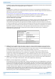
Contacting CommScope Hardware to Software Mapping Information 1 2 Scan the QR Code to the right to view or download the minimum software requirements for each of the DCCS hardware modules. Alternatively, you can go to the following web address to access the portal: https://www.commscope.com/resources/in-building-wireless/era Click on a document link to open it, or right click on the link and select the Save target as… option from the contextual menu.
Contacting CommScope CommScope ERA® CAP L2 with Fiber Interface Page 48 M0203A9B_uc © September 2022 CommScope, Inc.