CommScope ERA® CAP M2 with Fiber Interface 2nd Generation Medium Power Carrier Access Point Installation Guide • M0203AHA_uc • August 2022
DISCLAIMER This document has been developed by CommScope, and is intended for the use of its customers and customer support personnel. The information in this document is subject to change without notice. While every effort has been made to eliminate errors, CommScope disclaims liability for any difficulties arising from the interpretation of the information contained herein.
TABLE OF CONTENTS Document Overview .................................................................................................................................................................................. 1 Document Revision History .............................................................................................................................................................................. 1 Document Cautions and Notes.................................................................
Table of Contents Mobility Solutions Technical Training............................................................................................................................................................. 43 Accessing ERA Series User Documentation .................................................................................................................................................... 43 CommScope ERA® CAP M2 with Fiber Interface Page iv M0203AHA_uc © August 2022 CommScope, Inc.
D OCUMENT O VERVIEW This guide provides a product overview and installation instructions for CAP M2 fiber variants. Table 1 lists the supported CAP M2 fiber variants. Part Number Table 1.
Document Overview Abbreviations Used in this Guide AP Access Point ISDE Innovation, Sciences et Développement économique Canada AUX Auxiliary ISED Innovation, Science and Economic Development Canada C Celsius kg Kilogram CAN Central Area Node LED Light Emitting Diode CAP L 2 Low Power Carrier Access Point, Second Generation LPS Limited Power Source CAP M2 Medium Power Carrier Access Point, Second Generation MHz Megahertz Cat Category mm Millimeter CAT Copper Transport MMF Mul
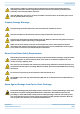
Document Overview High frequency radiation in operation. Risk of health hazards associated with radiation from the antenna(s) connected to the unit. Implement prevention measures to avoid the possibility of close proximity to the antenna(s) while in operation. If the CAP M2 power connector is not easily accessible, a disconnect device in the mains power circuit must be provided within easy reach. Property Damage Warnings Keep operating instructions within easy reach and make them available to all users.
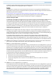
Document Overview Compliance 1 Notice: For installations, which have to comply with FCC RF exposure requirements, the antenna selection and installation must be completed in a way to ensure compliance with those FCC requirements.
Document Overview transmitter. Users and installers must be provided with antenna installation instructions and transmitter operating conditions for satisfying RF exposure compliance. French: Cet appareil est conforme avec Santé Canada Code de sécurité 6. Le programme d'installation de cet appareil doit s'assurer que les rayonnements RF n'est pas émis au-delà de I'exigence de Santé Canada. Les informations peuvent être obtenues: http://www.hc-sc.gc.ca/ewh-semt/pubs/radiation/radio_guide-lignes_direct-eng.
Document Overview 9 equipment in a residential area is likely to cause harmful interference in which case the user will be required to correct the interference at his own expense. Note: This unit complies with European standard EN62368-1. Equipment Symbols Used / Compliance Please observe the meanings of the following symbols used in our equipment and the compliance warnings listed in Table 2. Table 2.
Document Overview Maximum Output Power Levels Table 3 lists the frequencies and maximum power output for bands supported in the CAP M2 variants. Table 3. Maximum Power Output by Frequency Band DL Frequency Range Power Output [dBm] 35 L T 3410 – 3640 MHz 35 35 HT 3570 – 3800 MHz 35 C -Ba nd 3700 – 3980 MHz 35 Required Antenna Distances Table 4. Minimum Antenna Distances Model CAP M2 C-Band M0203AHA_uc © August 2022 CommScope, Inc.
Fiber CAP M2 Overview F IBER CAP M2 O VERVIEW This installation guide describes the Fiber CAP M2, which interfaces with a Classic CAN or TEN via an optical link. This allows the Fiber CAP M2 to provide data over Single-Mode Fiber (SMF) or Multi-Mode Fiber (MMF). Power for Fiber CAP M2s is provided over External AC/DC or remotely through hybrid fiber (see "Connect the Cables to the Fiber CAP M2” on page 28).
Fiber CAP M2 Overview Table 5. Function of the CAP M2 Connectors and LED Ref # Label Description Function 0 None Grounding Bolt Connects the CAP MX to an approved earth-ground source. Port 1 Port 1 OCTIS Connector Port to pass fiber cable to the SFP+ module. The port seal is the OCTIS Universal connector PN 7847069. Connecting the fiber cable to the CAP M2 requires removing the service lid. ANT 1 4.
Fiber CAP M2 Overview Mounting and Power Kits are described in the applicable installation process: Table 6.
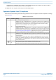
Fiber CAP M2 Overview Table 7. Supported SFP+ Modules (Continued) CommScope PN Description Maximum Range A 7 84 6 85 7 40km BIDI 40km Kit 1 x Attenuator, LC/UPC, 7dB A7843668 1 x 10G BIDI SFP+ TX1270/RX1330 40km A7832204 1 x 10G BIDI SFP+ TX1330/RX1270 40km A7832206 OCTIS™ Universal Lever Assembly Kits OCTIS™ is a trademark of Radiall. The following connector drawings and instructions were provided by Radiall. Scan the QR code to the right to watch the OCTIS SFP+ connector assembly video.
Fiber CAP M2 Overview Figure 2 and Figure 3 show the LC Duplex connector at the cable termination. The BiDi (single fiber) cable termination follows the same OCTIS assembly instructions. Figure 2. OCTIS Universal Lever Assembly Instructions CommScope ERA® CAP M2 with Fiber Interface Page 12 M0203AHA_uc © August 2022 CommScope, Inc.
Plan and Prepare for a Fiber CAP M2 Installation Figure 3. OCTIS Universal Lever Unmating Instructions P LAN AND P REPARE FOR A F IBER CAP M2 I NSTALLATION Do the following before beginning installation. 1 2 3 Review and know the information in "Maximum Number of Fiber CAP M2s Supported in an ERA System” on page 13. Review and know the information in "Safely Working with ERA Hardware” on page 2.
Plan and Prepare for a Fiber CAP M2 Installation Depending on the transmit bandwidth requirements, you can connect up to four CAP M 2s to each OPT Card. – Fiber CAP M2s must be connected to OPT Cards installed in Slots L1, L2, L3, or L4 in a TEN or Classic CAN. OPT Cards installed in WCS Slots L5 - L8 cannot be used to connect APs.
Plan and Prepare for a Fiber CAP M2 Installation CAP M2 Dimensions Use the dimensions shown in the section applicable to this installation to determine the space required at the mounting site. Figure 4. CAP M2 Mounting Dimensions CAP CAP M2 Weights Use the weights listed in Table 10 to determine a site that can bear the weight of the Fiber CAP L that is being installed, where: • • The “Maximum Lift Weight” is the highest weight that must be lifted during installation.
Plan and Prepare for a Fiber CAP M2 Installation Table 10. Maximum CAP M2 Installation Weights* CAP M2 configured with this kit … Single Mounting Bracket Maximum Lift Weight Total Hanging Weight kg lbs. kg lbs. 19 42 43.4 19.
Mount the Fiber CAP M2 M OUNT THE F IBER CAP M2 A Fiber CAP M2 is suitable for indoor and outdoor installations. Mounting instructions are divided into the sections listed below.
Mount the Fiber CAP M2 Wall Mount a CAP M2 The following sections provide the installation methodology and steps required to mount a Fiber CAP M2 to a wall. Mounting Orientation for Wall Mounts When wall mounting a Fiber CAP M2, the recommendations should be observed. Figure 5. Wall Mounting Orientation for a CAP M2 CommScope ERA® CAP M2 with Fiber Interface Page 18 M0203AHA_uc © August 2022 CommScope, Inc.
Mount the Fiber CAP M2 Mounting CAP M2 with a Wall Mounting Kit The following sections provide the installation methodology and steps required to mount a CAP M2 to a wall. When wall mounting a CAP M2, the recommendations should be observed. The CAP M2 must be installed with the antenna ports point downward. See "Mounting Orientation for Wall Mounts” on page 18. Table 11.
Mount the Fiber CAP M2 5 Secure the wall mount bracket to the wall, using four anchor screws. CommScope ERA® CAP M2 with Fiber Interface Page 20 M0203AHA_uc © August 2022 CommScope, Inc.
Mount the Fiber CAP M2 The anchor screws do not ship with the CAP M2 as the anchor type is dependent on the on-site conditions (wall structure and materials). Use screw anchors that are rated for the mounting surface. The hole for the screws in the bracket is 7.5 mm in diameter and will accommodate screws between 5.8 mm and 7.5 mm. 6 7 8 Confirm that the Wall Mount Bracket is securely fastened to the wall.
Mount the Fiber CAP M2 M5 screws 9 Confirm that the CAP M2 is securely attached to the Wall Mount Bracket.
Mount the Fiber CAP M2 Prepare for CAP M2 Hybrid Fiber Splice Box Kit Installation 1 2 3 Follow the steps in "Unpack and Inspect the CAP M2 and Optional Accessories” on page 16. Refer to "Determine the CAP M2 Installation Site” on page 14 to determine the mounting location, which must be able to support the weight and dimensions of the CAP M2. Refer to "Mounting Orientation for Wall Mounts” on page 18 to determine the mounting orientation of the CAP M2.
Mount the Fiber CAP M2 3 From the CAP M2 Hybrid Fiber Splice Box Kit, insert Fiber Patch Cord in one of the cable glands indicated in the graphic to the right. 4 Strip the insulation of the composite cable for 100 cm and the fibers for 90 cm, and then shorten the copper cables to 25 cm. 5 Insert the composite cable in the first cable gland and separate the multi-fibers cable from the copper wires. It is necessary to remove the nut to perform this action.
Mount the Fiber CAP M2 8 If a second splice holder is needed, it can be assembled using the M4 insulating washer and two M4 plain washers, as shown to the right. The required screw is a PTK30 x 12. 9 Remove the sealing nut and rubber of the cable gland and insert the optical cables. 10 Place each cable into one of the grooves of the seal insert. 11 Press the seal insert into the clamp ring opening. 12 Fix the optical cables inside the box using one cable tie and tight the sealing nut.
Mount the Fiber CAP M2 14 Close all unused grooves with the plastic cylinders, no matter if one or two cable glands are used. 15 Insert the copper wires in the first multiple terminal connectors. See markings on the internal support. Then fasten the copper cables inside the box using one cable tie. 16 Remove the sealing nut and insert the CAP M2 supply cable and tighten the sealing nut. 17 Connect the supply cable to the terminal strip and fix it inside the box using one cable tie.
Mount the Fiber CAP M2 Wall Mount a CAP M2 Using a CAP M2 Hybrid Fiber Splice Box Kit (optional) The steps in this section pertain only to those installations that require the use of the optional Hybrid Fiber Splice Box to provide fiber and power to the CAP M2. 1 2 3 4 5 6 Remove the Hybrid Fiber Box cover. Attach the Hybrid Fiber Splice Box to the Wall Bracket with the three captive screws already installed in the Splice Box. Replace the cover.
Connect the Cables to the Fiber CAP M2 C ONNECT THE C ABLES TO THE F IBER CAP M2 Complete the following procedures in the order in which they are presented. • • • • • "Ground the Fiber CAP M2 (Optional)” on page 28 "Connect the Passive RF Antenna” on page 32 "Connect the Fiber CAP M2 to a Classic CAN or TEN” on page 36 "Powering on a Fiber CAP M 2” on page 37 "Powering on a Fiber CAP M 2” on page 37. Do not remove protective caps from any of the connectors until instructed to do so.
Connect the Cables to the Fiber CAP M2 5 Attach the ring end of the wire to the chassis ground stud on the bottom, right side of the CAP M2, as shown in the graphic below. Chassis ground stud 6 7 Use the Keps nut removed in Step 4 to secure the ground wire to the chassis-ground stud. Route the free end of the chassis grounding wire to an approved (per local code or practice) earth ground source.
Connect the Cables to the Fiber CAP M2 Clean the RF Cable Connectors This section tells you how to clean RF cable connectors. The graphics in this section illustrate the cleaning procedure and do not show the CAP M2. This procedure requires the use of compressed air. Wear protective clothing—especially protective glasses—to protect against injury from flying particles. This procedure requires the use of flammable material. There is a risk of fire. Keep away from sources of ignition.
Connect the Cables to the Fiber CAP M2 4 Use a lint-free wipe drenched with isopropyl alcohol to clean the connector winding. 5 Use a cotton bud drenched with isopropyl alcohol to clean the lip of the inner ring. 6 Use a cotton bud drenched with isopropyl alcohol to clean the inside surface of the inner ring. 7 Use a cotton bud drenched with isopropyl alcohol to clean the inside of the center conductor spring tines.
Connect the Cables to the Fiber CAP M2 9 Use compressed air to remove metal chips and small particles from the mating and inner surfaces of the connector. 10 Use a lint-free wipe drenched with isopropyl alcohol to clean the winding area. 11 Use a cotton bud drenched with isopropyl alcohol to clean the inside mating surface of the inner ring. 12 Use a cotton bud drenched with isopropyl alcohol to clean the outside surface of the center pin.
Connect the Cables to the Fiber CAP M2 • • f 2 If the 50 coaxial cable has a push-pull connector, make sure the cable is seated firmly in the ANT 1, ANT 2, ANT 3 or ANT 4 connector. If the 50 coaxial cable has a threaded connector, torque the connector 5 N-m (3.69 ft-lb). Do not over-tighten the connector. Connect the other end of the 50 coaxial cable to the passive antenna installed in Step b. If necessary, repeat Step 1 on page 32 to connect a 50 coaxial cable to the other ANT connector.
Connect the Cables to the Fiber CAP M2 4 Insert the cable in the fiber optic port. Fiber optic cable inserted into CAP M 2 port 5 Replace the cover on the CAP M2. Installing SFP+ Modules in the CAP M2 See "SFP+ Module Kits” on page 10 for more information. 1 2 Install the hybrid splice box on the CAP M2 bracket. See "Mounting a CAP M2 with a Hybrid Fiber Splice Box Kit (optional)” on page 22. Loosen the eight torque screws on the cover located at the bottom of the CAP M2.
Connect the Cables to the Fiber CAP M2 3 Insert the SFP+ module into the port as shown below. 4 Feed the cable from the hybrid splice box through the CAP M2 port, as shown below, and assemble the OCTIS LC Universal connector and insert it into the CAP M2 port as shown in Figure 2. M0203AHA_uc © August 2022 CommScope, Inc.
Connect the Cables to the Fiber CAP M2 5 Connect the LC connector to the SFP+ module inside the CAP M2. 6 Replace the cover on the CAP M2. Connect the Fiber CAP M2 to a Classic CAN or TEN When using duplex fibers, the fiber paths need to be crossed. Ensure that the fiber connecting the CAP M2’s SFP Tx is connected to the CAN/TEN’s SFP Rx and the CAP M2’s SFP Rx is connected to the CAN/TEN’s SFP Tx. CommScope ERA® CAP M2 with Fiber Interface Page 36 M0203AHA_uc © August 2022 CommScope, Inc.
Powering on a Fiber CAP M 2 1 Connect the CAP M2 Optical Port 1 as appropriate for this installation. a b c d Remove the dust cap from the CAP M2 Optical Port 1 connector and the connectors on the SMF or MMF. Follow the local cleaning technique to clean Optical Port 1. Clean the connectors on the SMF or MMF following the fiber supplier’s recommendations. Install the SFP+ connector and Optical OCTIS Kit on the end of the SMF or MMF that will connect to the CAP M2.
Powering on a Fiber CAP M 2 connect to the AC power source. A 10 m (33.7 ft) AC power cable is also available as an option. The AC power cables for US and EU are shown in Figure 6 and Figure 7 respectively. Amphenol Protec ve 4-Pin female cap connector 3x end splice Black White Green 4 3 1 2 Mains connector Figure 6. CAP M2 AC Power Cable US Amphenol Protec ve 4-Pin female cap connector 3x end splice Blue Brown Yellow/Green 4 3 1 2 Mains connector Figure 7.
Powering on a Fiber CAP M 2 Amphenol Protec ve 4-Pin female cap connector 2x end splice Black 4 3 Red 1 CAP M 2 Mains connector Figure 8. CAP M2 DC Power Cable Connect the CAP M2 Power Do not connect or disconnect the power cable at the Mains connector while power is on. Turn off Mains power before connecting the power cable at the unit, then, engage mains power again.
Powering on a Fiber CAP M 2 4 5 6 7 With the cable's Mains plug disconnected from the CAP M, turn the circuit breaker on, unscrew the plug's protective cover, and carefully test the plug with a voltmeter to ensure that the voltage and polarity are correct. Once the testing has been completed, turn off the circuit breaker. Unscrew the protective cover from the Mains connector of the unit.
Powering on a Fiber CAP M 2 Power the CAP M2 The CAP M2 is powered on as soon as power is connected to it. Under normal operating conditions, the Power LED turns on briefly when the unit is first detected. It will then go out briefly, followed by an initialization period during which the Power LED flashes slowly while the CAP M2 is configured. The Power LED remains a steady green (not flashing) once the unit reaches a fully operational state, which typically occurs within 45 seconds.
Contacting CommScope C ONTACTING C OMM S COPE The following sections tell you how to contact CommScope for additional information or for assistance. CMS Global Technical Support The following sections tell you how to contact the CommScope Mobility Solutions (CMS) Technical Support team. Support is available 7 days a week, 24 hours a day. Telephone Helplines Use the following Helpline telephone numbers to get live support, 24 hours a day: 24x7 +1 888-297-6433 (Toll free for U.S.
Contacting CommScope Hardware to Software Mapping Information 1 2 Scan the QR Code to the right to view or download the minimum software requirements for each of the DCCS hardware modules. Alternatively, you can go to the following web address to access the portal: http://www.commscope.com/resources/in-building-wireless Click on a document link to open it, or right click on the link and select the Save target as… option from the contextual menu.
Contacting CommScope CommScope ERA® CAP M2 with Fiber Interface Page 44 M0203AHA_uc © August 2022 CommScope, Inc.