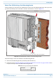
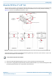
Installing CAP Ms Mount Two CAP Ms Using a Dual Mounting Bracket In this procedure you will mount two CAP Ms back-to-back in one Dual Mounting Bracket. The steps in this procedure will identify the two CAP Ms as CAP M-1 and CAP M-2, as shown in Figure 20. CAP M 1 (front of the CAP M-1 faces the moun ng surface) CAP M 2 (front of CAP M-2 faces out, and is back-to-back with CAP M 1) Figure 20.
Installing CAP Ms 3 Refer to "Determine the Mounting Site” on page 24 to determine the mounting location, which must be able to support the weight and dimensions of the CAP M. Installer must verify that the mounting surface will safely support the combined load of the electronic equipment and all attached hardware and components. 4 5 6 Refer to "Mounting Orientation” on page 34 to determine the mounting orientation of the CAP M.
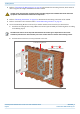
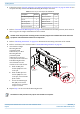
Installing CAP Ms 7 From both sides of CAP M-1: a b Loosen the M6 pins, leaving its washer in place. Remove the two M6 screws and their M6 plain and M6 split-lock washers; reserve the screws and washers as you will later reinstall them. Loosen the M6 pin Remove the M6x12 screw and its washers M6 plain washer M6 split-lock washer M6x12 screw M0201AJG_uc © Decemeber 2020 CommScope, Inc.
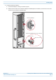
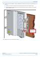
Installing CAP Ms 8 Use both handles on the CAP M-1 chassis to lift it above the Mounting Bracket, and with the front of the chassis facing the mounting surface, lower it into place. • • The M6 pins that you loosened in Step 7 on page 43 must align with the Mounting Bracket slots, as shown below. The washer for each M6 pin should be next to the CAP M-1 chassis (inside the bracket).
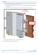
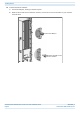
Installing CAP Ms 11 On lower right of the CAP M-1, reinstall the M6x12 screw and its washers that you removed in Step 7 on page 43. a b Slide first the M6 split-lock washer and then the M6 plain washer over the M6x12 screw. Insert the M6x12 screw through the screw hole shown below, and screw it back into the CAP M-1 chassis; torque to 11 N-m. M6x12 screw and washer set in hole closest to the moun ng surface 12 Repeat Step 11 on the left side of the CAP M-1.
Installing CAP Ms 13 From both sides of CAP M-2: a b Loosen the M6 pins, leaving its washer in place. Remove the two M6 screws and their washers; reserve the screws and washers as you will later reinstall them. Loosen the M6 pin Remove the M6 screw and its washer CommScope ERA® Medium Power Carrier Access Point Installation Guide Page 46 M0201AJG_uc © Decemeber 2020 CommScope, Inc.
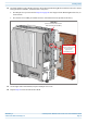
Installing CAP Ms 14 Use both handles on the CAP M-2 chassis to lift it above the Mounting Bracket with the back of its chassis facing the back of CAP M-1, and then lower it into place. • • The M6 pins that you loosened in Step 13 on page 46 must align with the Mounting Bracket slots, as shown below. The washer for each M6 pin should be next to the CAP M-2 chassis (inside the bracket).
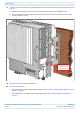
Installing CAP Ms 17 On lower right of the CAP M-2, reinstall the M6x12 screw and its washers that you removed in Step 13 on page 46. a b Slide first the M6 split-lock washer and then the M6 plain washer over the M6x12 screw. Insert the M6x12 screw through the screw hole shown below, and screw it back into the CAP M chassis; torque to 11 N-m. M6x12 screw and washer set in hole furthest from the moun ng surface 18 19 Repeat Step 11 on the left side of CAP M-2.
Installing CAP Ms Mount the CAP M to a 4" to 18" Pole This procedure is specific to the CAP M Pole Mounting Kit for Up to 18" Poles (CommScope PN 7692096-XX), which is used when mounting a CAP M to a pole with a circumference of 4" to 18" (10.2 cm to 45.8 cm). Figure 21 shows the assembled kit mounted to a pole. 4" to 18" (10.2 cm to 45.
Installing CAP Ms 3 Follow the steps in "Unpack and Inspect the CAP M and Optional Accessories” on page 29. Table 11 lists the parts that ship with the CAP M Pole Mounting Kit for Up to 18" Poles. Table 11.
Installing CAP Ms 9 Attach four of the threaded bolts to the side of the top Pole-Mounting Bracket that will face toward the pole (inside the Pole-Mounting Bracket). Install the M8 nut and washers in the order shown. a b c 10 11 12 9A 4" to 18" (10.2 cm to 45.8 cm) Threaded bolts 9B Torque the M8 Hexagon Nut to 27 N-m.
Installing CAP Ms Attach a Hybrid Fiber Splice Box to the CAP M The steps in this section pertain only to those installations that require the use of the optional Hybrid Fiber Splice Box to provide fiber and power to the CAP M. If the optional Hybrid Fiber Splice Box is not required for this installation, skip to "Grounding the CAP M” on page 56.
Installing CAP Ms 2 Remove the six neck screws (shown below) from the front cover of the Splice Box. 3 Open the Splice Box. 4 5 6 7 Attach an M4 x 25 pan-head screw to the upper hole, and a second M4 x 25 pan-head to the hole on the lower, right-hand side of the Splice Box. Close the Splice Box. Replace the six neck screws that you removed from the front cover of the Splice Box in Step 2 on page 53. Go to "Grounding the CAP M” on page 56. M0201AJG_uc © Decemeber 2020 CommScope, Inc.
Installing CAP Ms Attaching a Hybrid Fiber Splice Box for a Dual Mount Installation 1 2 Break the left-hand side hook of the Splice Box bracket. This is necessary for proper mounting. Hang the Splice Box onto the Dual Mounting Bracket on the left-hand side of the CAP M, as shown below. Dual Moun ng Bracket Hybrid Fiber Splice Box CommScope ERA® Medium Power Carrier Access Point Installation Guide Page 54 M0201AJG_uc © Decemeber 2020 CommScope, Inc.
Installing CAP Ms 3 Remove the six neck screws (shown below) from the front cover of the Splice Box. 4 Open the Splice Box. 5 6 7 8 Attach an M4 x 25 pan-head screw to the upper hole, and a second M4 x 25 pan-head to the hole on the lower, left-hand side (shown at right) of the Splice Box. Close the Splice Box. Replace the six neck screws that you removed from the front cover of the Splice Box in Step 3 on page 55. Go to "Grounding the CAP M” on page 56. M0201AJG_uc © Decemeber 2020 CommScope, Inc.
Installing CAP Ms Grounding the CAP M The CAP M must be grounded. Do not use the grounding bolts to connect an external device. 1 Connect an earth-bonding cable to the grounding bolt connections on the outside of the CAP M chassis, as shown below. Grounding bolts 2 3 4 5 Loosen the M6 hex nut(s), and then connect the earth-bonding cable between the two washers as shown to the right. Secure the earth-bonding cable by tightening the M6hex nut(s) that you loosened in the preceding step.
Installing CAP Ms Connect the CAP M Cables Complete the following procedures in the order in which they are presented. Unless otherwise noted, each procedure is applicable to a singular CAP M (not in a cascade), or to a Primary or Secondary CAP M in a cascade.
Installing CAP Ms Table 12.
Installing CAP Ms 2 Remove the protective cap from the RF connector. 3 Use compressed air to remove metal chips and small particles from the mating and inner surfaces of the connector. 4 Use a lint-free wipe drenched with isopropyl alcohol to clean the connector winding. 5 Use a cotton bud drenched with isopropyl alcohol to clean the lip of the inner ring. 6 Use a cotton bud drenched with isopropyl alcohol to clean the inside surface of the inner ring. M0201AJG_uc © Decemeber 2020 CommScope, Inc.
Installing CAP Ms 7 Use a cotton bud drenched with isopropyl alcohol to clean the inside of the center conductor spring tines. 8 Remove the protective caps from the unit connector, and then clean it the same way that you cleaned the cable connector. 9 Use compressed air to remove metal chips and small particles from the mating and inner surfaces of the connector. 10 Use a lint-free wipe drenched with isopropyl alcohol to clean the winding area.
Installing CAP Ms 12 Use a cotton bud drenched with isopropyl alcohol to clean the outside surface of the center pin. Connect the Antenna Cable(s) The following information regarding antenna mapping and is relevant to all CAP M variants. • • For Non-MIMO bands, there is no channel mapping option for the transceiver/antenna port. The transceiver/antenna port relationship is fixed in hardware.
Installing CAP Ms • 5 6 If the 50 coaxial cable has a threaded connector, torque the connector 5 N-m (3.69 ft-lb). Do not over-tighten the connector. Connect the other end of the 50 coaxial cable to the passive antenna installed in Step 2. For a MIMO installation, repeat Step 1 through Step 5 to connect an antenna cable to ANT2. Connect the CAP M to a Classic CAN or TEN Connect the CAP M Optical Port 1 as appropriate for this installation. Note the maximum range listed in Table 12.
Installing CAP Ms 3 4 Follow the local cleaning technique to clean Port A. Install an Ethernet OCTIS Kit on the end of the CAT cable that will connect to the Fiber CAP M, and then connect that end of the cable to Port A on the Fiber CAP M. (Refer to the technical data sheet that ships with the OCTIS Kit for further information.) Cat6A, including all Cat6A cables, Cat6A Patch Cords, and Patch Panels, between Port A on the Fiber CAP M and an auxiliary Ethernet device cannot exceed 3 meters (9.8 feet).
Installing CAP Ms Amphenol Protec ve 4-Pin female cap connector 3x end splice Black White Green 4 3 1 2 CAP M DC Power Cable CAP M Mains connector Figure 22. CAP M AC Power Cable The standard CAP M DC power cable is a 3.2 m (10.5 ft) 13 AWG cable with a 4-pin Amphenol C016 series plug on one end to connect to the CAP M Mains connector. The other end of the cable is unterminated with 2 end splices to connect to the -48 Vdc power source. The standard DC power cable is shown in Figure 23.
Installing CAP Ms Connect the Mains Power to the CAP M 1 2 Locate the Mains power cable that was delivered with the CAP M. Locate or install a suitable power junction box or receptacle near the unit and route the power cable from the power source to the CAP M. Do not connect the cable to the unit's Mains connector at this time. The power source must be interruptible. The Mains cable must be properly secured observing local regulations and electrical codes.
Installing CAP Ms Connect a Hybrid Fiber Splice Box For a CAP M powered by the Hybrid Fiber Splice Box (PN 7693816-xx): • • • connect the power cable to the proprietary 4-pin, 36 to 60 Vdc Power connector on the CAP M, and terminate the other end to the CAP M Hybrid Fiber Splice Box. Install an SFP+ module of the desired type (same as used at the OPT Card port) into the OCTIS connector before connecting the LC Fiber pigtail.
Replacing the Power Supply Unit (PSU) R EPLACING THE P OWER S UPPLY U NIT (PSU) If the PSU fails, you can replace the module at the site. There are two PSU types, VAC and VDC. Table 14. PSU Part Numbers PSU Part Number Description CAP M Model Name 7772503-00 PSU, VAC in / 28Vdc out 7835269-000x CAP M 6/6/7E/7E 7841092-00 PSU, VDC in / 28Vdc out 7835269-000x CAP M 6/6/7E/7E 7658962-01 VAC in / 31.
Replacing the Power Supply Unit (PSU) 6 Loosen the eight Torx T-10 screws on the PSU. The weight of the power supply must be supported as you loosen the screws to prevent damage to the supply. 7 Remove the PSU from the housing, being careful not to damage the wires. Do not attempt to support the weight of the supply with the attached input and output cables. Due to the short length of the cables, once the top of the PSU is clear of the housing, angle it downward to remove it.
Replacing the Power Supply Unit (PSU) 8 Place the PSU in the bench. 9 Remove the plastic connector guards that cover the connector blocks on either side of the PSU and set aside. You will need these later. M0201AJG_uc © Decemeber 2020 CommScope, Inc.
Replacing the Power Supply Unit (PSU) 10 Loosen the 3 Phillips head terminal screws for the Input connector and pull the connector upward to remove it. 11 Loosen two Phillips head terminal screws for the Output connector and pull the connector upward to remove it. Set aside the PSU for return to CommScope. 12 Place the replacement PSU next the CAP M with the two DC terminals on the left side and the three AC terminals on the right side.
Replacing the Power Supply Unit (PSU) CAUTION! Make sure the product label is upside down, the +30 VDC label is on the left and the VAC input is on the right as shown in the picture below. Failure to follow this orientation may cause damage to the PSU. 13 Reconnect the input and output connectors and tighten the associated terminal screws. CAUTION! The connector pins are to the side of the screws farthest from the CAP M housing for both connectors. These must be reassembled in the same location.
Replacing the Power Supply Unit (PSU) 15 Place the PSU into the housing, being careful not to pinch the wires. The supply must be supported until the eight captive power supply Torx T-10 screws have been tightened. 16 Tighten the eight Torx T-10 screws. The Torque value is 0.82Nm (7 inch pounds). CommScope ERA® Medium Power Carrier Access Point Installation Guide Page 72 M0201AJG_uc © Decemeber 2020 CommScope, Inc.
Replacing the Power Supply Unit (PSU) 17 Remount the CAP M. See “Mount the CAP M” on page 33. 18 Reconnect the cables to the CAP M. See “Connect the CAP M Cables” on page 57. 19 Switch on the Mains power and check the CAP M for proper operation. The green LED starts flashing slowly as the CAP M initializes and then turns steady when initialization is complete. Replacing the VDC PSU 1 2 3 4 5 Switch off the circuit breaker supplying power to the CAP M.
Replacing the Power Supply Unit (PSU) 6 Loosen the eight Torx T-10 screws on the PSU. The weight of the power supply must be supported as you loosen the screws to prevent damage to the supply. 7 Remove the PSU from the housing, being careful not to damage the wires. Do not attempt to support the weight of the supply with the attached input and output cables. Due to the short length of the cables, once the top of the PSU is clear of the housing, angle it downward to remove it.
Replacing the Power Supply Unit (PSU) 9 Remove the plastic guards from both connectors and set aside. You will need these later. 10 Loosen the 3 Phillips head terminal screws for the Input connector and pull the connector upward to remove it. M0201AJG_uc © Decemeber 2020 CommScope, Inc.
Replacing the Power Supply Unit (PSU) 11 Loosen two Phillips head terminal screws for the Output connector and pull the connector upward to remove it. Set aside the PSU for return to CommScope. 12 Place the replacement PSU next the CAP M with the two DC terminals on the left side and the three AC terminals on the right side. It is very important to confirm that the replacement supply is the same type as the original defective supply. The AC and DC supplies are not interchangeable.
Replacing the Power Supply Unit (PSU) CAUTION! Make sure the product label is upside down, the +35.5 VDC label is on the left and the -48 VDC is on the right. 13 Reconnect the input and output connectors and tighten the associated terminal screws. CAUTION! The connector pins are to the side of the screws farthest from the CAP M housing for both connectors. These must be reassembled in the same location. Failure to follow this instruction may result in damaged connectors. CAUTION! Make sure the +35.
Replacing the Power Supply Unit (PSU) 14 Place the plastic guard over both connectors. 15 Place the PSU into the housing, being careful not to pinch the wires. The supply must be supported until the eight captive power supply Torx T-10 screws have been tightened. CommScope ERA® Medium Power Carrier Access Point Installation Guide Page 78 M0201AJG_uc © Decemeber 2020 CommScope, Inc.
Replacing the Power Supply Unit (PSU) 16 Tighten the eight Torx T-10 screws. The Torque value is 0.82Nm (7 inch pounds). 17 Remount the CAP M. See “Mount the CAP M” on page 33. 18 Reconnect the cables to the CAP M. See “Connect the CAP M Cables” on page 57. 19 Switch on the Mains power and check the CAP M for proper operation. The green LED starts flashing slowly as CAP M initializes and then turns steady when initialization is complete. M0201AJG_uc © Decemeber 2020 CommScope, Inc.
Contacting CommScope C ONTACTING C OMM S COPE The following sections tell you how to contact CommScope for additional information or for assistance. CMS G LOBAL T ECHNICAL S UPPORT The following sections tell you how to contact the CommScope Mobility Solutions (CMS) Technical Support team. Support is available 7 days a week, 24 hours a day. Telephone Helplines Use the following Helpline telephone numbers to get live support, 24 hours a day: 24x7 +1 888-297-6433 (Toll free for U.S.
Hardware to Software Mapping Information H ARDWARE 1 2 TO S OFTWARE M APPING I NFORMATION Scan the QR Code to the right to view or download the minimum software requirements for each of the DCCS hardware modules. Alternatively, you can go to the following web address to access the portal: http://www.commscope.com/resources/in-building-wireless Click on a document link to open it, or right click on the link and select the Save target as… option from the contextual menu.
Accessing ERA User Documentation CommScope ERA® Medium Power Carrier Access Point Installation Guide Page 82 M0201AJG_uc © Decemeber 2020 CommScope, Inc.