
User's Manual
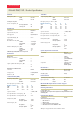

SPECIFICATIONS
Electrical
Mains power, Vac
................nominal..............100 to 240
................operating.............85 to 264
Vdc mails power not possible.
Power consumption, W
................max. temp., fully loaded.....770
................room temp., idle .........400
Optical Link
Connectors..................................E2000/APC 8°
Optical return loss, dB ......................45 min.
Fiber type,mm ..............................Single mode E9/125
Optical link budget, dB .....................0 to 10
Input power
@ OTRx master side, dBm
................1900 MHz ............+2.5 composite
................1700/2100 MHz.........+5.5 composite
................700 MHz .............+3 composite
Minimum BTS Input power, dBm..............
................1900 MHz ............-19.5
................1700/2100 MHz.........-16.5
................700 MHz .............-19
Additional DL gain (22 dB) available in case of low power BTS
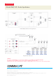
RF Interface
Master Unit
Number of connectors
................1900 MHz ............4
................1700/2100 MHz.........4
................700 MHz .............4
System optimized for BTS power, dBm
..................................33
..................................43
Antenna Port of Remote Unit
Connector ................ . . . . . . . . . . . . . . . . . N Female
Output power............. . . . . . . . . . . . . . . . . . See band specification
Return loss, dB ............ . . . . . . . . . . . . . . . . . 15 typical
1700/2100 MHz (AWS)
Frequency range, MHz
................Uplink ..............1710 to 1780
................Downlink .............2110 to 2180
RF output power per carrier *, dBm
Number of Carriers 1 2 4 8
CDMA 45.5 42.5 39.5 36.5
UMTS 45.5 42.5 39.5 36.5
LTE 45.5 42.5**** 39.5 36.5
Spurious emission ........ . . . . . . . . . . . . . . . . . <-13 dBm / 1 MHz
DL output tolerance over frequency, dB ........±1
DL output tolerance over temperature, dB .......±0.5**
UL Input ICP3, dBm
................ICP3 optimized ..........-12 min.
................Noise figure optimized ......-18 min.
UL Noise figure, dB
................ICP3 optimized ..........8
..................................11 max.
................Noise figure optimized ......4.5
..................................6 max.
1900 MHz
Frequency range, MHz
................Uplink ..............1850 to 1915
................Downlink ............1930 to 1995
RF output power per carrier *, dBm
Number of Carriers 1 2 4 8
GSM 42.5 39.5 36.5 33.5
CDMA 42.5 39.5 36.5 33.5
UMTS 42.5 39.5 36.5 33.5
LTE 42.5 39.5**** 36.5 33.5
Spurious emission......... . . . . . . . . . . . . . . . . . <-13 dBm / 1 MHz
DL output tolerance over frequency, dB ........±1
DL output tolerance over temperature, dB .......±0.5**
UL Input ICP3, dBm
................ICP3 optimized..........-12 min.
................Noise figure optimized......-18 min.
UL Noise figure, dB
................ICP3 optimized ..........8
..................................11 max.
................Noise figure optimized ......4.5
..................................6 max.
System Supervision and Control
Commands .................................RF on/off
..........................................External control ports
Alarms ..................................Summary
..................................Power supply
..................................Optical UL and DL failure
..................................Temperature
Supervision .................................Output power on a per-
..........................................channel and per-
..........................................band basis (optional)
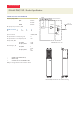
Mechanical***
Height, width, depth mm (in) ................831 x 156 x 147
..........................................(32.7 x 6.1 x 5.8)
Weight, kg (Ib) ........... . . . . . . . . . . . . . . . . . 20 (44)
Environmental
Operating temperature range...............-33° C to +50° C
Ingress protection ......RF part .............IP67
................Fan part .............IP55
Minimum SW Requirements for Basic Support
ION-M SW V7.0.1
Ordering Information
ION-M17EHP/19P .........................7714210
Depending on the selected options and the configuration the ordering material number contains
an identifying suffix.
Extension Unit Options
ION-M7P EU ...............................7601170
Other Extension Units possible on request
* PAR 7.5 dB @ 0.1 %
** With active cooling
*** Spacing required 40 mm (1.58 in) around unit
**** 2 dB reduction of Pout @ carrier bandwidth < 5 MHz
All figures are typical values unless otherwise stated.
ION-M17EHP/19P - Product Specification