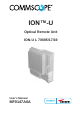
ION™-U Optical Remote Unit ION-U L 7/8/85/17/19 User's Manual MF0147A0A
DISCLAIMER: This document has been developed by CommScope, and is intended for the use of its customers and customer support personnel. The information in this document is subject to change without notice. While every effort has been made to eliminate errors, CommScope disclaims liability for any difficulties arising from the interpretation of the information contained herein.
Table of contents TABLE OF CONTENTS 1. GENERAL 7 1.1. USED ABBREVIATIONS 7 1.2. HEALTH AND SAFETY WARNINGS 8 ABOUT COMMSCOPE 11 1.3. 12 INTERNATIONAL CONTACT ADDRESSES FOR CUSTOMER SUPPORT INTRODUCTION 15 1.4. PURPOSE 15 1.5. THE ION-U L 7/8/85/17/19 REMOTE UNIT 15 2. FUNCTIONAL DESCRIPTION 17 2.1. SISO AND MIMO OPERATION 17 2.2. ION-U 7/8/85/17/19 PORTS 18 3. COMMISSIONING 20 3.1. 3.1.1. 3.1.2. MECHANICAL INSTALLATION General Wall-Mounting Procedure 20 20 21 3.2. 3.2.1.
Table of contents 4.3. STATUS LED ALARMS 41 4.4. EXTERNAL ALARM INPUTS 42 4.5. TROUBLESHOOTING 43 5. MAINTENANCE 44 5.1. GENERAL 44 5.2. RU POWER SUPPLY REPLACEMENT 45 6. APPENDIX 49 6.1. ILLUSTRATIONS 49 6.2. ELECTRICAL SPECIFICATIONS 50 6.3. ENVIRONMENTAL AND SAFETY SPECIFICATIONS 50 6.4. MECHANICAL SPECIFICATIONS 50 6.5. SPARE PARTS 51 7.
figures and tables FIGURES AND TABLES figure 3-2 Remote unit, SISO.................................................................................... 17 figure 3-3 Remote unit, MIMO Two units paired ....................................................... 17 figure 3-4 RU Connectors and Status LED ............................................................... 18 figure 4-1 Wall-mounting bracket .............................................................................. 21 figure 4-2 RU threaded pins...
figures and tables table 1-1 List of international contact addresses....................................................... 14 table 4-1 Specified torques ....................................................................................... 20 table 4-2: ION-U L 7/8/85/17/19 Connectors ............................................................ 27 table 4-3 AC power cable ......................................................................................... 29 table 4-4 DC power cable ...............
1 General 1. General 1.1.
1 General 1.2. Health and Safety Warnings 1. Danger: Obey all general and regional installation and safety regulations relating to work on high voltage installations, as well as regulations covering correct use of tools and personal protective equipment. 2. Danger: Laser radiation! Do not stare into the beam; do not view it directly or with optical instruments. 3. Danger: Before opening the unit, disconnect mains power. 4. Danger: Due to power dissipation, the remote unit may reach a very high temperature.
1 General PD (mW/cm²) is the allowed Power Density limit acc. to 47 CFR 1.1310 (B) for general population / uncontrolled exposures which is o F (MHz) / 1500 for frequencies from 300MHz to 1500MHz o 1 for frequencies from 1500MHz to 100.000MHz RF exposure compliance may need to be addressed at the time of licensing, as required by the responsible FCC Bureau(s), including antenna co-location requirements of 1.1307(b)(3). 12.
1 General Equipment Symbols Used Please observe the meanings of the following symbols used in our equipment: Symbol Page 10 Compliance Meaning --- Alert sign to R&TTE Symbol Indicates conformity with the R&TTE directive 1999/5/EC certified by the notified body no. 0700.
1 General About CommScope CommScope is the foremost supplier of one-stop, end-to-end radio frequency (RF) solutions. Part of the CommScope portfolio are complete solutions for wireless infrastructure from top-of-the-tower base station antennas to cable systems and cabinets, RF site solutions, signal distribution, and network optimization. CommScope has global engineering and manufacturing facilities. In addition, it maintains field engineering offices throughout the world.
1 General 1.3. International Contact Addresses for Customer Support Americas: Canada United States CommScope Canada Andrew LLC, A CommScope Company Mail 505 Consumers Road, Suite 803 Toronto M2J 4V8 Canada Mail 620 North Greenfield Parkway Garner, NC 27529 U.S.A. Phone +1-905-878-3457 (Office) +1-416-721-5058 (Cell) Phone +1-888-297-6433 Fax +1-905-878-3297 Fax +1-919-329-8950 E-mail Peter.Masih@commscope.com, wisupport.us@commscope.com E-mail wisupport.us@commscope.
1 General Europe: United Kingdom Scandinavia Andrew Wireless Systems UK Ltd Andrew Norway (AMNW) Mail Unit 15, Ilex Building Mulberry Business Park Fishponds Road Wokingham Berkshire RG41 2GY England Mail P.O. Box 3066 Osloveien 10 Hoenefoss 3501 Norway Phone +44-1189-366-792 Phone + 47 32-12-3530 Fax +44-1189-366-773 Fax + 47 32-12-3531 E-mail wisupport.uk@commscope.com E-mail wisupport@commscope.
1 General Czech Republic CommScope Solutions Czech Republic C-Com, spol. s r.o Mail U Moruší 888 53006 Pardubice Czech Republic Phone +49 871 9659171 (Office) +49 171 4001166 (Mobile) Fax +49 871 9659172 E-mail wisupport@commscope.com Africa & Middle East: Middle East & North Africa CommScope Solutions International Inc.
0 Introduction Introduction 1.4. Purpose Cellular telephone systems transmit signals in two directions between base transceiver station (BTS) and mobile stations (MS) within the signal coverage area. If weak signal transmissions occur within the coverage area because of indoor applications, topological conditions or distance from the transmitter, extension of the transmission range can be achieved by means of an optical distribution system.
0 Introduction The ION-U L 7/8/85/17/19 is capable of supporting both SISO and MIMO. RF signals are transported to the remote units via single mode fiber at 1310 nm. MIMO is achieved with the use of 4 fibers and the pairing of two interlinking RUs. The system includes an Automatic Gain Control (AGC) that avoids field adjustments and reduces design, installation, and optimization time. The ION is easily set-up and supervised via a graphical user interface (GUI).
2 Functional Description 2.
2 Functional Description 2.2. ION-U 7/8/85/17/19 Ports The RF, optical, mains power, alarm, power control, and expansion ports are located on the bottom of the RU as shown in figure 2-3.
2 Functional Description Optical Ports The LC-APC optical connectors are used to send and receive the signals between the RU and the Master Unit’s OTRx modules. The DL optical port G receives downlink signals from the MU OTRx. The UL optical port H transmits uplink signals to the MU OTRx. Mains Connector The RU receives its power through the Mains connector I . The type of connector is dependent on the RU model. A 4-pin Amphenol connector is used for AC models and standard DC models.
3 Commissioning 3. Commissioning 3.1. Mechanical Installation 3.1.1. General Read the health and safety warnings in chapter 1.2. 1. Warning: Do not install the unit in a way or at a place where the specifications outlined in the Environmental and Safety Specifications leaflet of the supplier are not met. 2. Warning: It is recommended to use the mounting hardware delivered by the manufacturer only.
3 Commissioning 3.1.2. Wall-Mounting Procedure 1. Check the suitability of the wall-mounting kit and the wall. 2. Install the wall-mounting bracket using 4 M6 screw anchors (not included*) according to the drilling layout. Confirm that the bracket is securely fastened to the wall. * The M6 screw anchors are not included as part of the RU delivery because the suitable type depends on the on-site conditions (wall structure and materials).
3 Commissioning 4. Install the Remote Unit on the wall-mounting bracket by lifting the RU into place and lowering it down onto the bracket. The M6 pins must align with the slots in the bracket to support the RU. B0303A8A figure 3-3 RU placed on wall mounting bracket 5. Fasten the lower section of the Remote Unit to the bracket using a washer and a M6x12 screw (on both sides). Slide a washer over each screw and then insert the screw and tighten it securely.
3 Commissioning 6. Fasten the Remote Unit to the bracket using a washer and M6 nut. Slide the washer over the threaded pins that were installed in step 3 and then screw the nut onto the pins (on both sides) and tighten securely. M6 nut Washer B0303AAA figure 3-5 Attach M6 nut to threaded pins 7. Confirm that all screws and nuts have been fastened and the unit is securely mounted to the wall.
3 Commissioning 3.2. Electrical Installation 3.2.1. General Read the health and safety warnings in chapter 1.2. 1. Warning: This unit contains dangerous voltages. Loss of life, severe personal injury, or property damage can be the result if the instructions contained in this manual are not followed. 2. Caution: It is compulsory to ground (earth) the unit before connecting the power supply. A grounding bolt is provided on the cabinet to connect the ground-bonding cable. 3.
3 Commissioning 11. Caution: For unstabilized electric networks, which frequently generate spikes, the use of a voltage limiting device is advised. 12. Caution: The unit complies with the surge requirement according to EN 61000-45 (fine protection); however, installation of an additional medium (via local supply connection) and/or coarse protection (external surge protection) is recommended depending on the individual application in order to avoid damage caused by overcurrent. 13.
3 Commissioning 3.2.2. Connections The ION-U RU ports and connectors shown below are located at the base of the RU. figure 3-7 ION-U L 7/8/85/17/19 Connectors Port/Conn LOCAL RS-232 STATUS PWR/CTRL ALARM EXPANSION UL Page 26 ION-U L 7/8/85/17/19 Connectors/Indicators Purpose This connector is used for external modem communication with an optional extension unit and for local connection to a laptop PC. This LED provides a visual warning of an alarm condition.
3 Commissioning Port/Conn EXPANSION DL ION-U L 7/8/85/17/19 Connectors/Indicators Purpose This connector is used to connect to the DL port of an expansion unit to provide additional bands of coverage OPTICS UL This connector is used to connect an optical fiber cable to send uplink signal back to the OTRx module of the ION-U master unit OPTICS DL This connector is used to connect an optical fiber cable to receive downlink signal from the OTRx module of the ION-U master unit MAINS This connector provides t
3 Commissioning 3.2.3. Grounding (Earthing) The RU must be grounded (earthed). 1. Connect an earth-bonding cable to the grounding bolt connection provided on the outside of the remote unit (near the Mains connector) as shown in figure 3-8. Do not use the grounding connection to connect external devices. figure 3-8 Grounding bolt figure 3-9 Grounding bolt, schematic view 2. After loosening the hex nut, connect the earth-bonding cable between the two washers as illustrated in the figures above. 3.
3 Commissioning 3.2.4. Mains Power Connection Before connecting electrical power to the units, the system must be grounded (earthed) as described in the previous chapter. The Mains power must be connected to the Mains connector of the unit for operation of the RU. A power cable is delivered with each RU. The type of power cable delivered is dependent on the type of power supply in the RU. The AC power cable is a 3.2 m (10.
3 Commissioning The Vdc/100 power cable is available for locations where the power drawn on each cable must be limited to a maximum of 100 VA. This cable is a 3.2 m (10.5 ft) 16 AWG cable with a 7-pin Amphenol C016 series plug on one end to connect to the RU Mains connector. The other end of the cable is un-terminated with 4 end splices to connect to the -48 vdc power source.
3 Commissioning 3. The Mains cable must be properly secured observing local regulations and electrical codes. Be sure to allow enough slack in the cable at the RU to plug or unplug the cable into the Mains connector of the RU. 4. Wire the power cable to the junction box or receptacle. Refer to the color code and pin numbers shown in figure 3-10 (AC cable), figure 3-11 (DC cable), or figure 3-12 (Vdc/100 cable) depending on the type of power supply used by the RU. 5.
3 Commissioning The selection of cable and antenna is an important consideration. On the one hand, a cable with higher loss is less expensive but, on the other hand, it impairs performance. Use an appropriate torque wrench for the coupling torque of N-type connectors (2 N-m / 20 in lb), with 13/16 in opening to tighten the N-type antenna connectors. For example, use torque wrench of item no. 244379 available from the CommScope e-catalog. Do NOT use your hands or any other tool (e.g.
3 Commissioning 1. Connect an RF cable with QMA male connectors between the UL Expansion port connector of the RU to the UL port of the expansion unit. Press the QMA connector of the cable onto the UL port of the RU until it clicks into place to connect the cable. 2. Connect an RF cable with QMA male connectors between the DL Expansion port connector of the RU to the DL port of the expansion unit.
3 Commissioning 7 7-Pin Binder 712 Series Pin Assignment 1 +V_FAN 2 Fan1 Alarm In 3 Fan1 (PWM) Out 4 GND_FAN 5 Fan2 Alarm In 6 Fan2 (PWM) Out 7 n.c 1 B303AMA table 3-7 Pwr/Ctrl Connector figure 3-17 Pwr/Ctrl Connector 3.2.9. Control Connector RS-232 - Local Interface This DB-9 female connector is used for external modem communication with a possible extension unit and for local connection with a laptop.
3 Commissioning 3.3. Optical-Fiber-Cable Connection - Rules Main optical system parameters: Fiber: Single mode fiber, type is 9.5/125 µm Fiber-cable connectors LC/APC ION-U system: The pigtails for the connection between Master Unit and Remote Unit must have a sufficient length. Protection for the optical fibers must be provided where the fibers feed into the units. The system attenuation of the optical fibers, including the connectors, must not exceed 5 dB.
3 Commissioning Connect the fiber-optic cables by inserting the cable end into the laser receptacle. Do not use any index-matching gels or fluids of any kind in these connectors. Gels are intended for laboratory use and attract dirt in the field. Note: Care should be taken when connecting and disconnecting fiberoptic cables - use the connector housing to plug or unplug a fiber. Scratches and dust significantly affect system performance and may permanently damage the connector.
3 Commissioning 3.3.1. Optical cable installation 1. Locate the Optics connector cover on the lower right side of the RU. Loosen the four cover screws, remove the cover, and set it aside. Removing this cover allows access to the UP and DL optical connectors. Optical Connectors Cover Screws figure 3-19 Remove optics cover 2. Remove the sealing nut from the optical cable gland at the bottom of the RU. Sealing nut figure 3-20 Remove sealing nut 3.
3 Commissioning Sealing nut figure 3-22 Insert fiber optic cables through sealing nut 5. Then insert the optical cables through the opening in the cable gland clamp ring 6. Connect the optical cables to the proper UL and DL LC/APC connectors. Connect LC/APC Optical Cables Clamp ring figure 3-23 Insert cables through clamp ring 7. Separate the two halves of the split-seal. Place each cable into one of the grooves in the lower half of the split-seal.
3 Commissioning 8. Press the split-seal up into the clamp ring opening. Split-seal Sealing nut figure 3-25 Press split-seal into opening 9. Tighten the sealing nut securely. Sealing nut figure 3-26 Tighten sealing nut 10. Replace the optics metal cover and tighten the four screws that were loosened in step 1. 3.3.2. Commissioning Read the health and safety warnings in chapter 3.3.
4 Alarms 4. Alarms 4.1. Bite and Alarms The Built-In Test concept comprises the monitoring of the power supplies, the power amplifiers, and the optical interface. All alarms that occur can be checked via software at the master unit. 4.2. Handling of Alarms As soon as the software acknowledges a valid alarm, a message is transmitted to the master unit. If the reason for the alarm has been cleared or if the alarm should continue, a new alarm message will not be repeated.
4 Alarms 4.3. Status LED Alarms For local supervision, a status LED on the connector panel of the remote unit adjacent to the Expansion ports provides a visual warning of an alarm condition. The color of the LED indicates the severity of the alarm. Detailed alarm information is available through the ION-U software interface. This table lists the alarm conditions and possible on-site measures that could be performed to resolve the issues responsible for triggering the alarms.
4 Alarms Alarm Name External 2 Alarm RF High Output CELL700 RF High Output CELL 850 RF High Output LMR 800 RF High Output PCS 1900E RF High Output AWS Power Supply 1 Alarm Power Supply 2 Alarm Power Supply 1 exceeded load threshold Power Supply 2 exceeded load threshold Power Supply 1 partial availability Power Supply 2 partial availability High Power Consumption Low Power Consumption Default Severity LED major Yellow major Green major Green major Green major Green major Green change/verify
4 Alarms 4.5. Troubleshooting The status of the remote unit can be checked via the master unit (for details please refer to the ION-U software manual). Locally, the status can be checked at the LED, see chapter 4.3 Status LED Alarms.
5 Maintenance 5. Maintenance 5.1. General Read the health and safety warnings in chapter 1.2. Note: The remote unit does not require preventative maintenance measures. Maintenance of the ION-U L 7/8/85/17/19 should be performed by replacing only components that are described in this chapter. In order to maintain the warranty, avoid unintentional damage to the seals on the modules. The spare parts list, includes only units that can be replaced in the field without tuning or soldering work.
5 Maintenance 5.2. RU Power Supply Replacement The power supply for the RU is a field replaceable module. The type of power supply used by the RU (AC, DC, or Vdc/100) is dependent on the model number of the RU. Before starting any maintenance on the RU, read the health and safety warnings in chapter 1.2 and the electrical installation general information in chapter 4.2.1. 1. Switch off the circuit breaker supplying power to the RU. 2.
5 Maintenance 4. Use a #2 Phillips head or slotted screwdriver to loosen the 8 universal slot/Phillips captive power supply screws and carefully remove the supply. The weight of the power supply must be supported as you loosen the screws to prevent damage to the supply. Loosen 8 universal slot/Phillips screws Mains connector figure 5-3 8 RU power supply screws 5. Carefully remove the power supply from the unit. Do not attempt to support the weight of the supply with the attached input and output cables.
5 Maintenance 8. Locate the output connector for the power supply on the left side of the supply. 9. Loosen the 2 Phillips head screws and remove the output connector. figure 5-6 RU power supply output cable 10. Remove the defective supply. figure 5-7 Ru with power supply removed 11. Replace the defective power supply with the new power supply. It is very important to confirm that the replacement supply is the same type as the original supply. The AC, DC, and Vdc/100 supplies are not interchangeable. 12.
5 Maintenance 13. Insert the power supply into the RU carefully to avoid damaging any cables. The supply must be supported until the 8 universal slot/Phillips captive power supply screws have been tightened. 14. Tighten the 8 universal slot/Phillips captive power supply screws. figure 5-9 Ru insert power supply 15. Reconnect the Mains power plug. 16. Switch on the breaker and check the RU for proper operation.
6 Appendix 6. Appendix 6.1.
6 Appendix 6.2. Electrical Specifications Please refer to the “ION-U_LP_RU_US_PA-106156-EN.GB.pdf” data sheet for the Remote Unit’s electrical specifications. 6.3. Environmental and Safety Specifications Please refer to the “ION-U_LP_RU_US_PA-106156-EN.GB.pdf” data sheet for the Remote Unit’s environmental and safety specifications. 6.4. Mechanical Specifications Please refer to the “ION-U_LP_RU_US_PA-106156-EN.GB.pdf” data sheet for the Remote Unit’s mechanical specifications.
7 Index 6.5. Spare Parts The following table lists the spare parts available for the Remote Unit. The configuration of the delivered unit meets the requirements of the customer and can differ depending on the state of the delivery. Maintenance of the ION-U L 7/8/85/17/19 should be performed on an FRU (Field Replaceable Unit) basis only. Do not damage the warranty labels on the components, as this voids the warranty.
7 Index 7. Index A H Abbreviations .......................................................... 7 ALARM ................................................................. 27 Alarm connector ................................................... 20 Alarm port ....................................................... 27, 34 Alarms Bite and Alarms ............................................... 41 External Inputs ................................................. 43 Handling of Alarms ...............................