® ION -U H 7P/80-85P/17(E)P/19P Remote Unit Manual MF0200A8D
DISCLAIMER: This document has been developed by CommScope, and is intended for the use of its customers and customer support personnel. The information in this document is subject to change without notice. While every effort has been made to eliminate errors, CommScope disclaims liability for any difficulties arising from the interpretation of the information contained herein.
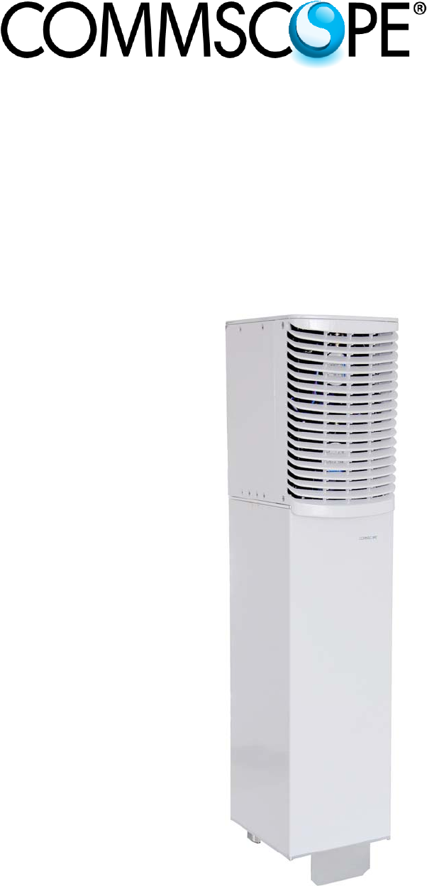
Table of Contents TABLE OF CONTENTS 1. GENERAL 6 1.1. USED ABBREVIATIONS 6 1.2. HEALTH AND SAFETY 7 1.3. PROPERTY DAMAGE WARNINGS 7 1.4. COMPLIANCE 8 1.5. ABOUT COMMSCOPE 12 1.6. INTERNATIONAL CONTACT ADDRESSES FOR CUSTOMER SUPPORT 13 2. INTRODUCTION 15 2.1. PURPOSE 15 2.2. ION-U HIGH POWER REMOTE UNITS 15 3. FUNCTIONAL DESCRIPTION 16 4. COMMISSIONING 17 4.1. GENERAL 17 4.2. 4.2.1. 4.2.2. 4.2.3. 4.2.4. 4.2.5.
Table of Contents 4.3.15.2. Connect Opus short plug to RU 4.3.15.3. Disconnect Opus short plug from RU 4.3.16. Optional equipment for optical fiber connection 45 46 46 4.4. 47 COMMISSIONING FLOW-CHART 5. ALARMS 49 5.1. BITE AND ALARMS 49 5.2. TROUBLESHOOTING 49 5.3. STATUS LED ALARMS 49 5.4. EXTERNAL ALARM INPUTS AND OUTPUTS 50 6. MAINTENANCE 51 6.1. GENERAL 51 6.2. REPLACING THE FAN UNIT 52 6.3. CLEANING THE HEAT SINK 53 7. APPENDIX 54 7.1. ILLUSTRATIONS 54 7.2.
Figures and Tables FIGURES AND TABLES figure 3-1 ION-U High Power RU block diagram ........................................................ 16 figure 4-1 Wall mounting - pitches .............................................................................. 19 figure 4-2 Pole mounting - pitches .............................................................................. 20 figure 4-3 Pole mounting - screw bands .....................................................................
1. General 1. General 1.1.
1. General 1.2. Health and Safety 1. Danger: Electrical hazard. Danger of death or fatal injury from electrical current. Obey all general and regional installation and safety regulations relating to work on high voltage installations, as well as regulations covering correct use of tools and personal protective equipment. 2. Danger: Electrical hazard. Danger of death or fatal injury from electrical current inside the unit in operation. Before opening the unit, disconnect mains power. 3.
1. General 7. Notice: Read and obey all the warning labels attached to the unit. Make sure that all warning labels are kept in a legible condition. Replace any missing or damaged labels. 8. Notice: Only license holders for the respective frequency range are allowed to operate this unit. 9. Notice: Make sure the repeater settings are correct for the intended use (refer to the manufacturer product information) and regulatory requirements are met.
1. General 3. Notice: Installation of this equipment is in full responsibility of the installer, who has also the responsibility, that cables and couplers are calculated into the maximum gain of the antennas, so that this value, which is filed in the FCC Grant and can be requested from the FCC data base, is not exceeded. The industrial boosters are shipped only as a naked booster without any installation devices or antennas as it needs for professional installation. 4.
1. General 6. Notice: The unit complies with Overvoltage Category II. It also complies with the surge requirement according to EN 61000-4-5 (fine protection); however, installation of an additional medium (via local supply connection) and/or coarse protection (external surge protection) is recommended depending on the individual application in order to avoid damage caused by overcurrent.
1. General Equipment Symbols Used / Compliance Please observe the meanings of the following symbols used in our equipment and the compliance warnings: Symbol --- Compliance FCC CE Meaning / Warning Unit is for FCC Part 20 purposes - COMMERCIAL MOBILE SERVICES – only. WARNING: This is NOT a CONSUMER device. It is designed for installation by FCC LICENSEES and QUALIFIED INSTALLERS. You MUST have an FCC LICENSE or express consent of an FCC Licensee to operate this device.
1. General 1.5. About CommScope CommScope is the foremost supplier of one-stop, end-to-end radio frequency (RF) solutions. Part of the CommScope portfolio are complete solutions for wireless infrastructure from top-of-the-tower base station antennas to cable systems and cabinets, RF site solutions, signal distribution, and network optimization. For patents see www.cs-pat.com. CommScope has global engineering and manufacturing facilities.
1. General 1.6. International Contact Addresses for Customer Support Canada United States CommScope Canada Andrew LLC, A CommScope Company Mail 505 Consumers Road, Suite 803 Toronto M2J 4V8, Canada Mail 620 North Greenfield Parkway Garner, NC 27529, U.S.A. Phone +1-905-878-3457 (Office) +1-416-721-5058 (Cell) Phone +1-888-297-6433 Fax +1-905-878-3297 A Fax E-mail wisupport@commscope.com Caribbean & South American Region CommScope Cabos do Brasil Ltda.
1. General United Kingdom Scandinavia Andrew Wireless Systems UK Ltd Andrew Norway (AMNW) Mail Unit 15, Ilex Building Mulberry Business Park Fishponds Road Wokingham Berkshire RG41 2GY, England Mail P.O. Box 3066 Osloveien 10 Hoenefoss 3501 Norway Phone +44-1189-366-792 Phone + 47 32-12-3530 Fax +44-1189-366-773 Fax + 47 32-12-3531 E-mail wisupport.uk@commscope.com E-mail wisupport@commscope.
2. Introduction 2. Introduction 2.1. Purpose Mobile telephone systems transmit signals in two directions between base transceiver station (BTS) and mobile stations (MS) within the signal coverage area to carry voice and data traffic. If weak signal transmissions occur within the coverage area because of indoor applications, topological conditions or distance from the transmitter, extension of the transmission range can be achieved by means of an optical distributed antenna system (DAS).
3. Functional Description The unit utilizes a single fiber to support multiple bands in both the uplink and downlink directions. WDM (Wave Division Multiplex) filters are integrated in the optical modules. For the UL, a wavelength within 1546 nm – 1550 nm is used. For the DL, a wavelength of 1310 ±10 nm is used. The maximum optical output power for the UL and DL is 6.7 mW. 3.
4. Commissioning 4. Commissioning 4.1. General Read and observe chapter 1.2 Health and Safety as well as the description carefully to avoid mistakes and proceed step by step as described. Do not operate the Remote Unit without terminating the antenna connectors. The antenna connectors may be terminated by connecting them to their respective antennas or to a dummy load.
4. Commissioning 5. Notice: Ensure that there is free access to the electrical connections as well as to the cabinet. The approved bending radius of the connected cables must not be exceeded. See chapter 7.1 for more details. 6. Notice: If any different or additional mounting material is used, ensure that the mounting remains as safe as the mounting designed by the manufacturer. The specifications for stationary use of the Remote Unit must not be exceeded.
4. Commissioning 4.2.3. Wall mounting procedure Notice: It is the responsibility of the installer to verify that the supporting surface will safely support the combined load of the electronic equipment and all attached hardware and components and to ensure that the RU is safely and securely mounted. 1. Mark the position of the drilling holes (for pitches refer to figure 4-1 Wall mounting). Drill four holes at the marked positions and insert dowels*. 2.
4. Commissioning 4.2.4. Pole mounting procedure with screw bands Standard mounting hardware cannot be used to mount the Remote Unit to a pole, a column, or other similar structures. Additional hardware must be used for this type of installation. The pole-mounting kit includes two mounting brackets with screw bands, (worm gear) clamps to mount the brackets to the pole and two M8x25 screws, flat washers, and split lock washers per bracket to attach the Remote Unit to the bracket. A 775 min. 788 max.
4. Commissioning 3. Hang the Remote Unit into the upper bracket, insert it into the lower bracket, and fasten it to the lower bracket with the M8x25 screws (C), split lock washers (D) and washers (E), see chapter 4.2.3. The maximum diameter of the pole or column must not exceed 120 mm (4.7 inch). ax. 120 m figure 4-5 Pole mounting – max. diameter 4.2.5.
4. Commissioning figure 4-7 Pole mounting - pitches figure 4-8 Pole mounting - brackets figure 4-9 Pole mounting - fasten RU 1. Apply this procedure to both mounting brackets on both sides: Screw a hexagon nut (E) to the threaded bolt and place a flat washer (F)) on it. Insert this side of the bolt into the mounting bracket (A). Then, fasten the mounting bracket with a flat washer (F), split lock washer (G), and the locking nut (D). See figure 4-6 Pole mounting – with brackets. 2.
4. Commissioning 4.3. Electrical Installation 4.3.1. Health and Safety for electrical installation Read and observe the notices in chapter 1.2 Health and Safety. 1. Danger: Electrical hazard. Danger of death or fatal injury from electrical current. Obey all general and regional installation and safety regulations relating to work on high voltage installations, as well as regulations covering correct use of tools and personal protective equipment. 4.3.2.
4. Commissioning 4.3.3. Connections The ION-U RU ports and connectors shown in the following are located at the base of the RU.
4. Commissioning Port/Conn A B C EXPANSION EXTERNAL ALARM IN/OUT RS 485 / +28V D LOCAL INTERFACE E ANT F STATUS G OPTICAL H PROBE I Grounding Bolts J MAINS ION-U High Power RU Connectors/Indicators Purpose Type This connector is used to interconnect to an Extension Unit to provide additional bands of coverage. Radiall Opus M424400003 This connector provides two alarm contact inputs and two alarm contact outputs.
4. Commissioning J figure 4-11 ION-U H 7P/80-85P/17(E)P/19P DC version connector flange Port/Conn ION-U High Power RU Connectors/Indicators Purpose All, except MAINS The connectors and indicators for the AC and the DC version are identical except for the MAINS connector. MAINS This connector provides the power to RU models that use standard DC (-60 to -48 Vdc) power.
4. Commissioning 4.3.4. Grounding (Earthing) The RU must be grounded (earthed). When double grounding lugs are used they must support M6 studs with a stud hole spacing of 15.88 mm (5/8”). 1. Connect an earth-bonding cable to one or both of the grounding bolt connections provided on the connector flange of the Remote Unit. Do not use the grounding connection to connect external devices. figure 4-12 Grounding bolts figure 4-13 Grounding bolt, schematic view 2.
4. Commissioning 4.3.5. Connection of the antenna cable The Remote Unit has one 4.3-10 type antenna connector labeled “ANT”. When attaching the antenna cable connector, it is recommended to refer to the corresponding documentation of the connector manufacturer. The bending radius of the antenna cable must remain within the given specifications. The selection of cable and antenna is an important consideration.
4. Commissioning 4.3.6. Cleaning procedure for RF cable connectors The figures in this chapter illustrate the cleaning procedure and do not show the actual RU. 1. What is needed for the cleaning? a. Isopropyl alcohol b. Compressed air c. Lint-free wipe d. Cotton buds 2. Remove protective cap from the RF connector. Caution: Risk of injury by flying particles when compressed air is used. Wear protective clothing, especially protective glasses. 3.
4. Commissioning 5. Clean the lip of the inner ring with a cotton bud drenched with isopropyl alcohol. 6. Clean the inside surface of the inner ring with a cotton bud drenched with isopropyl alcohol. 7. Clean the inside of the center conductor spring tines with a cotton bud drenched with isopropyl alcohol. 8. Clean in the similar way the connector of the connected cable. Remove protective caps from the unit connector first.
4. Commissioning 9. Remove metal chips and small particles from the mating and inner surfaces of the connector using compressed air. 10. Continue with the winding area using lint-free wipe drenched with isopropyl alcohol. 11. Continue with the inside mating surface of the inner ring. 12. Clean the outside surface of the center pin.
4. Commissioning 4.3.7. Antenna cable connector assembly 1. What is needed for the connector assembly? a. Torque wrench. b. (Adjustable) counter wrench 2. Join the connectors and turn the coupling nut until the thread grips. 3. Push in the connector until it clicks. 4. Fasten the coupling nut hand-tight. Do not turn the connector but the coupling nut only.
4. Commissioning 5. Retain the cable connector with the counter wrench and fasten the Torque wrench coupling nut with the torque wrench until the torque is applied (torque wrench clicks). Counter wrench For angled antenna connectors use your hand to retain the cable connector and fasten the coupling nut with the torque wrench. Make sure only the coupling nut is turned, not the cable connector. 4.3.8.
4. Commissioning Pin PE Pin1 Pin3 Pin2 figure 4-14 Mains power connector figure 4-15 Mains power cable - AC The Mains cable is part of the delivery. It’s available in two wiring configurations: Prot ect ive Cap Pin 1 2 3 PE Wiring 1 Name Color Phase Black Neutral White n.c. n.c Ground Green Pin 1 2 3 PE Wiring 2 Name Color Phase Brown Neutral Blue n.c. n.c Ground Green/Yellow table 4-3 AC power cable pinning For the AC power supply connection, a minimum cross section of 1.5 mm2 is required.
4. Commissioning 4.3.8.2. Mains power connection DC Caution: Danger of electrical hazard by high current. Disconnect mains power before opening the DC connector housing. Note: The Mains cable must be properly secured observing local regulations and electrical codes. Be sure to allow enough slack in the cable at the RU to mount or dismount the cable into the DC Mains connector of the RU. Unscrew the two M3 x 12 captive screws and take off the cover from the DC Mains connector housing.
4. Commissioning First, install a conduit fitting (not contained in scope of delivery) to the 34.52 mm hole. This must be a suitable fitting for a 1 Inch conduit with lock nut. Inside, the clearance around the hole is 5 mm, the maximum space for the nut is 8 mm. Then, insert your wiring through the opening and mount it to the M6 mains terminals. Observe the correct polarity. Close the conduit fitting to ensure water tightness.
4. Commissioning 4.3.9. Extension Unit port connection The Expansion connector is used to connect a cable bridge to an optional Extension Unit to provide additional bands of coverage. This port provides control and RF signaling to and from the Extension Unit. Attention: The cable bridge connector is a push-pull connector. Ensure not to insert it at an angle into the EU connector. The connector coupler has to be inserted before the Pin-holder is pushed in. Otherwise the connectors might be damaged.
4. Commissioning 4.3.10. External alarm In / Out port The Alarm port provides external alarm contacts (two inputs and two outputs) that are used to monitor and report alarms generated by other equipment or to provide contact closures for RU alarms. The connector is an 8-pin Binder 712 series connector.
4. Commissioning 4.3.12. Local interface port The Local Interface port is a RJ45 network port, which can be used for a local connection to a laptop PC. This interface is used by factory for the initial setup of the RU. Front View figure 4-20 Local interface connector Pin 1 2 3 4 5 6 7 8 RJ45 Assignment TXD+ TXDRXD+ RXD- table 4-6 Local interface connector pinning 4.3.13.
4. Commissioning 4.3.14. Optical-fiber cable connection Main optical system parameters: Fiber: Single mode fiber, type is E9/125 µm Attenuation: <0.36 dB / km @ 1310 nm / Dispersion: <3.5 ps / nm km @ 1310 nm / Fiber-cable connectors LC/APC8° <0.26 dB / km @ 1550 nm <18.0 ps / nm km @ 1550 nm The pigtails for the connection between Master Unit and Remote Unit must have a sufficient length. Protection for the optical fibers must be provided where the fibers feed into the units.
4. Commissioning Connect the fiber-optic cables by inserting the cable end into the laser receptacle and aligning the key (on the cable end) with the keyed slot. Do not use any index-matching gels or fluids of any kind in these connectors. Gels are intended for laboratory use and attract dirt in the field. Notice: Care should be taken when connecting and disconnecting fiber-optic cables use the connector housing to plug or unplug a fiber.
4. Commissioning 4.3.15. Assembly instructions for optical LC patch cables The ION-U H 7P/80-85P/17(E)P/19P utilizes a single fiber cable for both uplink and downlink. The RU optical connector (Opus short plug kit) supports both simplex (one fiber cable) and duplex (two fiber cables) operation. The Opus short plug kit, which is included with the delivery of the RU, has the following components.
4. Commissioning 4.3.15.1. Assemble optical Opus short plug components The following instructions cover both simplex and duplex fiber cables. Steps that apply only to duplex cables have “b” following the step number. 1 Unscrew the nut and take out the plug clamp. Slide the adaptor nut clamp 2 onto and along the fiber patch cable as shown.
4. Commissioning Note: 3 The LC latch must be pressed down in order to slide it into the cavity of the LC support. Insert the LC connector by its side into Cavity A of LC support 5 until it clicks into place. 3b Insert the LC connectors by their sides into the LC support 5 until they click into place. Ensure that the channel positioning is correct as shown.
4. Commissioning 5 Screw the adapter nut 1 onto the body (2 N-m maximum torque). figure 4-30 Tighten Opus short plug adapter nut 4.3.15.2. Connect Opus short plug to RU 1 Pull on the plug’s collar to remove the protection cap. Protective cap figure 4-31 Remove Opus short plug protective cap 2 Push the plug body into the receptacle until the collar is in the locked position.
4. Commissioning 4.3.15.3. Disconnect Opus short plug from RU 1 To disconnect the Opus short plug, pull on the collar to release the plug. figure 4-33 Disconnect Opus short plug from RU 4.3.16.
4. Commissioning 4.4.
4.
5. Alarms 5. Alarms 5.1. Bite and Alarms The Built-In Test concept comprises the monitoring of the power supplies, the power amplifiers, fan units and the optical interface. All occurring alarms can be checked via software at the Master Unit. As soon as the software acknowledges a valid alarm, a message is transmitted to the Master Unit. If the reason for the alarm has been cleared or if the alarm should continue, a new alarm message will not be repeated.
5. Alarms 5.4. External Alarm Inputs and Outputs The eight-pin EXT ALARM IN/OUT connector supports two external alarm inputs and two external alarm outputs. Chapter 4.3.10 External alarm In / Out port includes the connector’s pin-out information and chapter 4.3.3 Connections identifies the connector’s location. The alarm outputs are realized with relays (switching capacity max. 60 VDC, max. 2 A, max 60 W). They can be used to monitor alarms with an external alarm indicator.
6. Maintenance 6. Maintenance 6.1. General Read and observe the notices in chapter 1.2 Health and Safety. Caution: Rotating fans. Risk of injury in operation. Wear tight-fitting clothes and disconnect mains before connecting or replacing or cleaning the fan unit. Caution: The unit reaches high temperature in operation. Risk of burns by hot surface. Do not touch the unit before it has sufficiently cooled down. Note: Note: The Remote Unit does not require preventative maintenance measures.
6. Maintenance 6.2. Replacing the Fan Unit Replacement of the fan unit is not required as a preventative measure. Only when an alarm indicates a malfunctioning of a fan, must the unit be exchanged. Note: Please observe that the fan unit can only be replaced as a whole. Do not remove the fans separately. Read and observe chapter 1.2 Health and Safety as well as the instructions in chapter 6.1 General before starting with the replacement. 1. Switch off the Remote Unit.
6. Maintenance 6.3. Cleaning the Heat Sink Note: Read and observe chapter 1.2 Health and Safety as well as the instructions in chapter 6.1 General before starting with the replacement procedure. Then, proceed as follows: 1. Switch off the Remote Unit. Make sure that mains power is disconnected for the following procedure. 2. Remove the fan cover and fan unit from the Remote Unit as described in chapter 6.2 Replacing the Fan Unit. Caution: Risk of injury by flying particles when compressed air is used.
7. Appendix 7. Appendix 7.1. Illustrations 176 824 Airf low 12.5 75 R4 5m in. 150 92 Power IN Cable Prot ective Tube Kit 21 R4 5 mi n. .
7. Appendix 7.2. Specifications This manual is valid for the following Remote Units: ID No 7698400-xxxx* 7698400-0001 7698400-0002 7698400-0003 7698400-0004 Denomination ION-U H 7P/80-85P/17P/19P ION-U H 7P/80-85P/17P/19P VAC ION-U H 7P/80-85P/17P/19P VDC ION-U H 7P/80-85P/17EP/19P VAC ION-U H 7P/80-85P/17EP/19P VDC * The xxxx suffix is the identifier for the specific configuration of the Remote Unit. Please refer to the ION-U H 7P/80-85P/17EP/19P data sheet for the ION-U HP RU specifications. 7.3.
8. Index 8. Index A H Alarm In/Out port .................................................... 38 Alarm port ............................................................... 25 Alarms External Inputs .................................................. 50 Handling of Alarms ............................................ 49 List ..................................................................... 49 Outputs .............................................................. 50 RU.....................................