OPERATIONS / MAINTENANCE MANUAL For 400MHz Fiber Optic Fed & RF Fed Bi-Directional Amplifier AE04A-D1248-001 AE04A-D1246-001 800MHz Fiber Optic Fed & RF Fed Bi-Directional Amplifier AE04A-D1437-002 AE04A-D1436-002 MANUAL NO.
INTRODUCTION ....................................................................................................................................... 5 Scope...........................................................................................................................................................................5 Purpose.......................................................................................................................................................................
5.7 5.8 6. 6.1 7. 7.1 7.2 +48V Power Supply Module (AE04A-D0803-002) ..................................................................................49 5.7.1 Description ......................................................................................................................................49 5.7.2 Specification....................................................................................................................................49 5.7.3 Photographs .........................
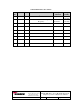
AMENDMENT RECORD SHEET Rev N . Date ECN Reason Page Amended A 6/16/04 1st Issue B 6/18/08 800 MHz Re-band to New Operating Frequency Wireless Innovations Group 2601 Telecom Parkway Richardson, Texas 75082 DWG NO: AE04B-A1669 2, 9, 10, 11, 29 and 36 Incorpor ated By J. Hsu/ E. Yearby K. Black/ E.
INTRODUCTION Scope This handbook is for use solely with the equipment identified by the Andrew Part Numbers shown on the front cover. It is not to be used with any other equipment unless specifically authorized by Andrew Corporation. Purpose The purpose of this handbook is to provide the operator/maintainer with sufficient information to operate, maintain and repair the equipment while in the filed.
GLOSSARY OF TERMS ALC AC BDA C/N DC dB dBc dBm ESD EMI FC/APC GND HPA Hz kHz kM LED LPA MHz mW nm NF OIP3 Ω RF Rx Tx V VAC VSWR Automatic Level Control Alternating Current Bi-Directional Amplifier Carrier-to-Noise Ratio Direct Current Decibel Decibel Below Carrier Decibel referenced to 1 mW Electrostatic Discharge Electromagnetic Interference Fiber Connector /Angle Polish Connector Ground High Power Amplifier Hertz Kilohertz Kilometer Light Emitting Diode Low Power Amplifier Megahertz Milliwatt nanometer N
1.0 SAFETY CONSIDERATIONS 1.1 Electric Shock Hazard To avoid electric shock, switch the BDA “OFF” prior to performing any repairs. All repairs beyond modular replacement must be performed by Andrew Trained Technicians. 1.2 Hot Surface Hazard RF power into the BDA will be limited by the use of high power attenuators. These attenuators will be located at the transmitter source. Caution should be taken when working near high power attenuators due to the risk of being burned by its hot surface.
2.0 EQUIPMENT OVERVIEW / DESCRIPTION MBTA System Wide Radio Tunnel Antenna Distribution System provides extended radio coverage within MBTA rail transit tunnels. The new tunnel antenna system is a two-way communication system consisting of 400 MHz base transceiver stations, 800 MHz base transceiver stations, antennas, radiating cable, fiber optic cable and BDAs. Both the 400 MHz and 800 MHz systems operate independently.
3.1 Parts Lists 3.1.1 400 MHz Bi-Directional Amplifier Andrew Part Number AE04A-D1264-001 AE04A-D1442-001 AE04A-D1443-001 AE04A-D1100-009 AE04A-D0803-002 AE04A-D0805-007 Description Qty. Section 2 1 1 1 1 1 5.1 5.2 5.3 5.6 5.7 5.8 Qty. Section 2 1 1 1 1 5.4 5.5 5.6 5.7 5.8 400 MHz EO Cell Amplifier Module 480 MHz High Isolation Duplexer 480 MHz Low Isolation Duplexer1 Fiber Optic Transceiver Module +48V Power Supply Module Alarm Module (Optional Equipment) 1.Used in RF Fed BDA. 3.1.
Notes: 1.Via Front Panel RS232 Connector. 2. Two-Tone Intermodulation: Measured two-output carriers at +20.0 dBm/C (+19.0 dBm/C for RF Fed BDA) at 483.1625 MHz and 483.2375 MHz with a BDA gain setting of 48 dB. 3.2.2 400 MHz Bi-Directional Amplifier Uplink Specification PARAMETER Operating Frequency Range Pass Bandwidth Gain Typical Output Gain Adjustment1 Composite Output Power Composite Input Power (With ALC Activated) Impedance VSWR OIP32 Noise Power max.
OIP32 Noise Power max. @ 48dB Gain AC Power +44 dBm -64 dBm/Hz (-110 dBm/Hz; RF Fed BDA) 120 VAC Single Phase Notes: 1.Via Front Panel RS232 Connector. 2. Two-Tone Intermodulation: Measured two-output carriers at +23.5 dBm/C (+16.8 dBm/C for RF Fed BDA) in the 851 – 856 MHz band, with a BDA gain setting of 48 dB. 3.2.
PARAMETERS Operating Temperature Operating Relative Humidity Dry Storage Temperature ESD & EMI1 Shock, Vibration and Moisture Resistance2 SPECIFICATION -20°C to +60°C 5% to 95% (Non-Condensing) -25°C to +60°C IEC 65 (Secretariat) 129 Draft Pub. 801-2 MIL-STD810(E) Notes: 1. Electromagnetic Compatibility (ESD) Part 2. 2. Shock-Method 516.4 Procedure I (20g’s), Vibration-Method 514.4 Category 1, Moisture Resistance-Method 506.3 Procedure II. 4.0 EQUIPMENT PHOTOGRAPHS 4.
4.
5.0 MODULES 5.1 400 MHz EO Cell Amplifier Module (AE04A-D1264-001) 5.1.1 Description This 2Watt, 483 - 487 MHz, class A Power Amplifier Module provides a nominal 52 dB of gain. It has 30 dB of gain adjustment range, which can be varied electronically thru the front panel RS232 connector. Additionally, the module has an internal Automatic Level Control (ALC) circuit, which can be set to limit the maximum power level produced by the BDA.
5.1.2 Specification PARAMETER Operating Frequency Range Gain Typical Output Gain Adjustment1 Composite Output Power Impedance VSWR OIP32 Noise Power max. @ 51.5 dB Gain DC Power Operating Temperature SPECIFICATION 483.1625 – 486.2375 MHz 51.5 dB 30 dB ≥ +33.5 dBm 50 Ohms 2:1 ≥ + 47.5 dBm -111.5 dBm/Hz + 48 VDC -20°C to +60°C Note: 1.Via Front Panel RS232 Connector. 2.Two-Tone Intermodulation: Measured two-output carriers of +23.5 dBm/C at 483.1625 MHz and 483.2375 MHz with 51.5 dB gain setting. 5.1.
Wireless Innovations Group 2601 Telecom Parkway Richardson, Texas 75082 DWG NO: AE04B-A1669 400/800 MHz Fiber Optic & RF Fed Bi-Directional Amplifier Operations / Maintenance Manual Rev: B Date: 06/18/2008 Page:16 of 63
5.1.
INTENTIONALLY LEFT BLANK Wireless Innovations Group 2601 Telecom Parkway Richardson, Texas 75082 DWG NO: AE04B-A1669 400/800 MHz Fiber Optic & RF Fed Bi-Directional Amplifier Operations / Maintenance Manual Rev: B Date: 06/18/2008 Page:18 of 63
INTENTIONALLY LEFT BLANK Wireless Innovations Group 2601 Telecom Parkway Richardson, Texas 75082 DWG NO: AE04B-A1669 400/800 MHz Fiber Optic & RF Fed Bi-Directional Amplifier Operations / Maintenance Manual Rev: B Date: 06/18/2008 Page:19 of 63
INTENTIONALLY LEFT BLANK Wireless Innovations Group 2601 Telecom Parkway Richardson, Texas 75082 DWG NO: AE04B-A1669 400/800 MHz Fiber Optic & RF Fed Bi-Directional Amplifier Operations / Maintenance Manual Rev: B Date: 06/18/2008 Page:20 of 63
INTENTIONALLY LEFT BLANK Wireless Innovations Group 2601 Telecom Parkway Richardson, Texas 75082 DWG NO: AE04B-A1669 400/800 MHz Fiber Optic & RF Fed Bi-Directional Amplifier Operations / Maintenance Manual Rev: B Date: 06/18/2008 Page:21 of 63
INTENTIONALLY LEFT BLANK Wireless Innovations Group 2601 Telecom Parkway Richardson, Texas 75082 DWG NO: AE04B-A1669 400/800 MHz Fiber Optic & RF Fed Bi-Directional Amplifier Operations / Maintenance Manual Rev: B Date: 06/18/2008 Page:22 of 63
INTENTIONALLY LEFT BLANK Wireless Innovations Group 2601 Telecom Parkway Richardson, Texas 75082 DWG NO: AE04B-A1669 400/800 MHz Fiber Optic & RF Fed Bi-Directional Amplifier Operations / Maintenance Manual Rev: B Date: 06/18/2008 Page:23 of 63
INTENTIONALLY LEFT BLANK Wireless Innovations Group 2601 Telecom Parkway Richardson, Texas 75082 DWG NO: AE04B-A1669 400/800 MHz Fiber Optic & RF Fed Bi-Directional Amplifier Operations / Maintenance Manual Rev: B Date: 06/18/2008 Page:24 of 63
Wireless Innovations Group 2601 Telecom Parkway Richardson, Texas 75082 DWG NO: AE04B-A1669 400/800 MHz Fiber Optic & RF Fed Bi-Directional Amplifier Operations / Maintenance Manual Rev: B Date: 06/18/2008 Page:25 of 63
5.2 480 MHz High Isolation Duplexer (AE04A-D1442-001) 5.2.1 Description The 480 MHz, high isolation duplexer provides the high bandpass selectivity and isolation for the Uplink and the Downlink frequency. The duplexer is based on a 5-cavity cross-coupled bandpass filter design and is aligned carefully during production to optimise the insertion loss, selectivity, and VSWR The duplexer is a fully passive device and should have an extremely long troublefree working life and requires no maintenance.
5.2.3 Photograph 5.3 480 MHz Low Isolation Duplexer (AE04A-D1443-001) 5.3.1 Description The 480 MHz, low isolation duplexer provides the band selectivity and isolation for the Uplink and the Downlink frequency. The duplexer is based on 4 ceramic coaxial resonators design and is aligned carefully during production to optimize the insertion loss, isolation, and VSWR The duplexer is a fully passive device and should have an extremely long troublefree working life and requires no maintenance.
5.3.3 Photograph 5.4 800 MHz EO Cell Amplifier Module (AE04A-D1265-001) 5.4.1 Description This 2Watt, 806-856 MHz, class A Power Amplifier Module provides a nominally 51 dB of gain. It has 30 dB of gain adjustment range, which can be varied electronically thru the front panel RS232 connector. Additionally, the module has an internal Automatic Level Control (ALC) circuit, which can be set to limit the maximum power level produced by the BDA.
5.4.2 Specification PARAMETER Operating Frequency Range Gain Typical Output Gain Adjustment1 Composite Output Power Impedance VSWR OIP32 Noise Power max. @ 51 dB Gain DC Power Operating Temperature SPECIFICATION 806 – 856 MHz 51 dB 30 dB ≥ +33 dBm 50 Ohms 2:1 ≥ + 47 dBm -111 dBm/Hz +48 VDC -20°C to +60°C Note: 1.Via Front Panel RS232 Connector. 2.Two-Tone Intermodulation: Measure at two-output carriers of +23.5 dBm/C at 845 MHz and 845.6 MHz with 51 dB gain setting. 5.4.
5.4.
INTENTIONALLY LEFT BLANK Wireless Innovations Group 2601 Telecom Parkway Richardson, Texas 75082 DWG NO: AE04B-A1669 400/800 MHz Fiber Optic & RF Fed Bi-Directional Amplifier Operations / Maintenance Manual Rev: B Date: 06/18/2008 Page:31 of 63
INTENTIONALLY LEFT BLANK Wireless Innovations Group 2601 Telecom Parkway Richardson, Texas 75082 DWG NO: AE04B-A1669 400/800 MHz Fiber Optic & RF Fed Bi-Directional Amplifier Operations / Maintenance Manual Rev: B Date: 06/18/2008 Page:32 of 63
INTENTIONALLY LEFT BLANK Wireless Innovations Group 2601 Telecom Parkway Richardson, Texas 75082 DWG NO: AE04B-A1669 400/800 MHz Fiber Optic & RF Fed Bi-Directional Amplifier Operations / Maintenance Manual Rev: B Date: 06/18/2008 Page:33 of 63
INTENTIONALLY LEFT BLANK Wireless Innovations Group 2601 Telecom Parkway Richardson, Texas 75082 DWG NO: AE04B-A1669 400/800 MHz Fiber Optic & RF Fed Bi-Directional Amplifier Operations / Maintenance Manual Rev: B Date: 06/18/2008 Page:34 of 63
INTENTIONALLY LEFT BLANK Wireless Innovations Group 2601 Telecom Parkway Richardson, Texas 75082 DWG NO: AE04B-A1669 400/800 MHz Fiber Optic & RF Fed Bi-Directional Amplifier Operations / Maintenance Manual Rev: B Date: 06/18/2008 Page:35 of 63
5.5 800 MHz High Isolation Duplexer (AE04A-D1438-002) 5.5.1 Description The 800 MHz, high isolation duplexer provides the high bandpass selectivity and isolation for the Uplink and the Downlink frequency. The duplexer is based on a 5-cavity cross-coupled bandpass filter design and is aligned carefully during production to optimize the insertion loss, selectivity, and VSWR The duplexer is a fully passive device and should have an extremely long troublefree working life and requires no maintenance.
5.5.3 Photograph 5.6 Fiber Optic Transceiver Module (AE04A-D1100-009) 5.6.1 Description The Fiber Optic Transceiver Module converts the Downlink and Uplink electrical (RF) signals into optical signals prior to routing the signals between remote BDAs and the base transceiver station. The fiber optic transceiver is capable of providing up to 18 dB of RF gain.
5.6.
5.6.
5.6.
INTENTIONALLY LEFT BLANK Wireless Innovations Group 2601 Telecom Parkway Richardson, Texas 75082 DWG NO: AE04B-A1669 400/800 MHz Fiber Optic & RF Fed Bi-Directional Amplifier Operations / Maintenance Manual Rev: B Date: 06/18/2008 Page:41 of 63
INTENTIONALLY LEFT BLANK Wireless Innovations Group 2601 Telecom Parkway Richardson, Texas 75082 DWG NO: AE04B-A1669 400/800 MHz Fiber Optic & RF Fed Bi-Directional Amplifier Operations / Maintenance Manual Rev: B Date: 06/18/2008 Page:42 of 63
INTENTIONALLY LEFT BLANK Wireless Innovations Group 2601 Telecom Parkway Richardson, Texas 75082 DWG NO: AE04B-A1669 400/800 MHz Fiber Optic & RF Fed Bi-Directional Amplifier Operations / Maintenance Manual Rev: B Date: 06/18/2008 Page:43 of 63
INTENTIONALLY LEFT BLANK Wireless Innovations Group 2601 Telecom Parkway Richardson, Texas 75082 DWG NO: AE04B-A1669 400/800 MHz Fiber Optic & RF Fed Bi-Directional Amplifier Operations / Maintenance Manual Rev: B Date: 06/18/2008 Page:44 of 63
INTENTIONALLY LEFT BLANK Wireless Innovations Group 2601 Telecom Parkway Richardson, Texas 75082 DWG NO: AE04B-A1669 400/800 MHz Fiber Optic & RF Fed Bi-Directional Amplifier Operations / Maintenance Manual Rev: B Date: 06/18/2008 Page:45 of 63
INTENTIONALLY LEFT BLANK Wireless Innovations Group 2601 Telecom Parkway Richardson, Texas 75082 DWG NO: AE04B-A1669 400/800 MHz Fiber Optic & RF Fed Bi-Directional Amplifier Operations / Maintenance Manual Rev: B Date: 06/18/2008 Page:46 of 63
INTENTIONALLY LEFT BLANK Wireless Innovations Group 2601 Telecom Parkway Richardson, Texas 75082 DWG NO: AE04B-A1669 400/800 MHz Fiber Optic & RF Fed Bi-Directional Amplifier Operations / Maintenance Manual Rev: B Date: 06/18/2008 Page:47 of 63
INTENTIONALLY LEFT BLANK Wireless Innovations Group 2601 Telecom Parkway Richardson, Texas 75082 DWG NO: AE04B-A1669 400/800 MHz Fiber Optic & RF Fed Bi-Directional Amplifier Operations / Maintenance Manual Rev: B Date: 06/18/2008 Page:48 of 63
5.7 +48V Power Supply Module (AE04A-D0803-002) 5.7.1 Description The AC to DC Power Supply Module provides + 48VDC from the main AC source to the BDA Chassis. The power supply module contains an AC front-end FARM (Filter/Autoranging Rectifier Module) followed by a DC-DC Converter Module. The AC to DC power supply module is capable of interfacing directly with various sources of AC power. The power supply module is equipped with a EMI filter, a autorange line rectifier and a inrush current limiting circuit.
5.7.
5.7.
5.8 Alarm Module (AE04A-D0805-007): Optional 5.8.1 Description The optional Alarm Module serves as a communication processor to provide a single point of monitoring interface for all the modules within the Fiber Optical Fed BDA. The summary alarm/monitoring status of each module can then be provided over Alarm Module’s RS-232 interface or sent thru the Fiber Optic Transceiver Module to a remote control location. In the unlikely event of failure, the entire Alarm Module should be replaced. 5.8.
Wireless Innovations Group 2601 Telecom Parkway Richardson, Texas 75082 DWG NO: AE04B-A1669 400/800 MHz Fiber Optic & RF Fed Bi-Directional Amplifier Operations / Maintenance Manual Rev: B Date: 06/18/2008 Page:53 of 63
5.8.
INTENTIONALLY LEFT BLANK Wireless Innovations Group 2601 Telecom Parkway Richardson, Texas 75082 DWG NO: AE04B-A1669 400/800 MHz Fiber Optic & RF Fed Bi-Directional Amplifier Operations / Maintenance Manual Rev: B Date: 06/18/2008 Page:55 of 63
INTENTIONALLY LEFT BLANK Wireless Innovations Group 2601 Telecom Parkway Richardson, Texas 75082 DWG NO: AE04B-A1669 400/800 MHz Fiber Optic & RF Fed Bi-Directional Amplifier Operations / Maintenance Manual Rev: B Date: 06/18/2008 Page:56 of 63
INTENTIONALLY LEFT BLANK Wireless Innovations Group 2601 Telecom Parkway Richardson, Texas 75082 DWG NO: AE04B-A1669 400/800 MHz Fiber Optic & RF Fed Bi-Directional Amplifier Operations / Maintenance Manual Rev: B Date: 06/18/2008 Page:57 of 63
6. INSTALLATION 6.1 BDA Installation & Gain Setup INSTALLATION 1 Install the BDA in a standard 19” rack. The BDA should be placed in a location where the interconnect cables (i.e. fiber, RF and serial cable) can be easily installed and not susceptible to damage. If the BDA is not installed in a controlled environment, a 5U high space should be located above and below the unit for airflow. 2 Plug the BDA into a 120 VAC single phase three wire grounded receptacle (5-15R).
3 If the measured output signal level exceeds +30 dBm, reduce the fiber optic gain (i.e. adjust BDA’s fiber optic transceiver front panel potentiometer) so that the output power level is equal to +30 dBm. NOTE: No additional fiber gain adjustment will be required after the fiber optic gain has been set. If any additional gain adjustments are required they must be performed via the RS232 port. The RF fed BDA gain setting is performed at the factory and no field adjustments are required.
NOTE: No additional fiber gain adjustment will be required after the fiber optic gain has been set. If any additional gain adjustments are required they must be performed via the RS232 port. The RF fed BDA uplink gain setting was performed at the factory and no field adjustments are required. For a 48 dB gain setting, the maximum input signal level is – 14 dBm with ALC active and – 43 dBm without ALC active.
7.3 Tools & Test Equipment The minimum tools and test equipment listed below are needed to successfully service the BDA: Spectrum Analyzer: Signal Generator: Attenuator: Optical Meter: Test cable x 2: Test cable x 2: Hand tools: 100kHz to 2GHz 30MHz to 2GHz 20dB, 10W, DC-2GHz, (N male – N female) Universal Volt-Watts N male – N male, 2M long RG214 SMA male – N male, 1m long RG223 Philips tip screwdriver SMA torque wrench 7.
7.4.3 Alarm Module Removal (Optional Equipment) Not applicable if alarm module is not being used. 1 2 3 4 5 6 Verify AC power to the BDA has been removed. Disconnect the system RF and Fiber Optic cables. Loosen the screws and remove the blank front plate right of the Alarm module. Loosen the module top and bottom wedge locks using a 9/64” allen wrench. Loosen the module front plate screws. Slowly but firmly, pull the module straight out of the chassis.
7.4.6 BDA Connections When tightening RF Type-N connectors located on the rear of the BDA, use a dedicated NType torque wrench. If Type-N connectors are over-tightened, irreparable damage will occur. Do not use adjustable pliers to loosen or tighten connectors. When connecting or disconnecting the fiber optic cable connectors located on the front panel of the fiber optic transceiver module, exercise caution not to touch the optical connector center pin.