ATC200-Lite Teletilt® Remote Control Variable Electrical Downtilt System Installation and Operation User Guide Andrew Corporation Base Station Antennas 2601 Telecom Parkway Richardson, Texas 75082-3521 Tel: (214) 631-0310 Fax: (214) 631-4706 www.andrew.
NOTICE The installation, maintenance, or removal of an antenna requires qualified, experienced personnel. Andrew installation instructions are written for such installation personnel. Antenna systems should be inspected once a year by qualified personnel to verify proper installation, maintenance, and condition of equipment. Andrew disclaims any liability or responsibility for the results of improper or unsafe installation practices. Do not install near power lines.
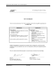
Revision History Revision No. Date Description of Changes None May 2005 Released.
ATC200-Lite Teletilt® Remote Control Downtilt System ii May 2005 Bulletin 639510
ATC200-Lite Teletilt® Remote Control Downtilt System Bulletin 639510 May 2005 iii
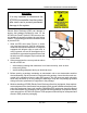
ATC200-Lite Teletilt® Remote Control Downtilt System WARNING It is very important to disconnect the ATC200-Lite controller from the system after each use to prevent permanent damage to the system. Electric Static Discharge (ESD) can damage or destroy the hardware equipment used for the ATC200-Lite Teletilt® System. ESD can occur during handling of equipment without the user feeling a shock. The following precautions should be taken to prevent ESD. 1.
ATC200-Lite Teletilt® Remote Control Downtilt System 5. Always avoid unnecessary movement of body, such as scuffing feet across flooring, when handling ESDS equipment. Such movement will generate additional charges of static electricity. 6. When removing or replacing ESDS equipment, hold the device or assembly through the electrostatic-free wrap, where possible. If this is not possible, lift the device or assembly by its body only.
ATC200-Lite Teletilt® Remote Control Downtilt System This page intentionally left blank.
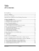
Table of Contents Revision History..................................................................................................... i Letter of Compliance............................................................................................. ii Declaration of Conformity.................................................................................... iii Important Notice and Electric Static Discharge Precautions................................. iv Section 1 Controller Setup......................
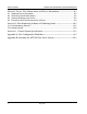
Table of Contents ATC200-Lite Teletilt® Remote Control Downtilt System Section 9 Device Test, Alarm Status and Device Information............................9-1 9.1 9.2 9.3 9.4 Obtaining Device Information...................................................................................... 9-2 Retrieving Current Alarm Status.................................................................................. 9-2 Clearing All Alarms on a Device...............................................................
Section 1 Controller Setup 1.1 System Description The ATC200-Lite series control system consists of an antenna system controller, actuators attached to the antennas (one for each variable tilt adjuster on an antenna), junction boxes/ splitters to daisy chain up to 32 actuators to a controller, and control cable assemblies. See Section 10 for details on component part numbers and ordering information.
Section 1–Controller Setup ATC200-Lite Teletilt® Remote Control Downtilt System 2. Connect the supplied 24Vdc or 12Vdc power converter to the dc IN port on the controller (Figure 1-1). IMPORTANT NOTE: The power converter used will affect both the 12Vdc and 24Vdc connector pins. For example, if a 24Vdc power converter is used, both the 12Vdc and the 24Vdc connector pins will transmit 24Vdc power. 3.
ATC200-Lite Teletilt® Remote Control Downtilt System Section 1–Controller Setup Antenna Field Installed Actuator ATM200-001 Junction Box ATJB200-A01-007 (Up to 32 antennas can be daisy-chained by using multiple junction boxes.
Section 1–Controller Setup ATC200-Lite Teletilt® Remote Control Downtilt System This page intentionally left blank.
Section 2 Program Installation 2.1 Program Download and Installation 1. Download the zip file containing the ATC200-Lite setup file from the Andrew Corporation web site (www.andrew.com). This zip file can be placed in any directory on the PC’s local C:\ drive. 2. Unzip the downloaded file to extract the ATC200-Lite setup file and its supporting installation documentation. 3. Double click on the setup file (eg. ATC200LiteSetup2_0.exe) to begin the installation process.
Section 2–Program Installation ATC200-Lite Teletilt® Remote Control Downtilt System Figure 2-3. Setup Introduction Screen. Figure 2-4. Installation Settings Screen.
ATC200-Lite Teletilt® Remote Control Downtilt System Section 2–Program Installation Figure 2-5. Completing Setup Screen. 2.2 Software Upgrades and Antenna Definition File Updates Software upgrades containing updated antenna definition files will be available to download from Andrew’s web site. Follow the steps discussed in Section 2.1 to download, unzip, and install ATC200-Lite software upgrades. Note that registered users will receive e-mail notifications alerting them of new software releases.
Section 2–Program Installation ATC200-Lite Teletilt® Remote Control Downtilt System This page intentionally left blank.
Section 3 Program Startup and Configuration 3.1 Preparing for Program Startup This program is designed to configure and control Andrew’s ATC200-Lite Teletilt®, AISG1 compliant, RET antenna system through a controller connected to a local PC. 1. Verify that the ATC200-Lite controller is turned off/powered down, etc. 2. Verify that the actuator/antenna is properly connected to the ATC200-Lite controller. 3.
Section 3–Program Startup and Configuration ATC200-Lite Teletilt® Remote Control Downtilt System 3.2 Serial Port Selection at Program Startup 1. The install process places an icon for the program on the desktop (Figure 3-2). 2. Double click on the icon, shown in Figure 3-2, to start the program. If the PC is connected to the controller on serial port 1, and if serial port 1 has been made available to the program by the PC, the program will select that port by default.
ATC200-Lite Teletilt® Remote Control Downtilt System Section 3–Program Startup and Configuration 4. If this occurs, use the ‘Communication’ menu located at the top of the main screen to select an available serial port. Make certain that the controller is connected to the port selected (Figure 3-5). Figure 3-5. Selecting a Serial Port. 5. If a port is selected that is not available for use by the program, the program will prompt the user to select a different port (Figure 3-6). 6.
Section 3–Program Startup and Configuration ATC200-Lite Teletilt® Remote Control Downtilt System 3.3 Beginning Program Operation After program startup and serial port selection, note the text displayed at the bottom of the screen in the ‘Command Status/Response’ window (Figure 3-3). This window is used to display the current status of the program, the progress of various commands that have been initiated by the user, and the final results of commands, such as success or failure messages. 3.
ATC200-Lite Teletilt® Remote Control Downtilt System Section 3–Program Startup and Configuration Go to ‘Tools, Antenna Files’ to upload antenna definition files. This feature can be used to upload newer versions of antenna definition files. This feature is rarely needed, since the ATC200-LITE unit automatically loads the latest antenna file during installation. Figure 3-8. Selecting ‘Antenna Files’ from Main Menu . Click the drop down arrow to view the list of antenna files.
Section 3–Program Startup and Configuration ATC200-Lite Teletilt® Remote Control Downtilt System This page intentionally left blank.
Section 4 Device Discovery and Addressing 4.1 Device Search After an antenna definition file has been loaded, automatically during program installation or manually by the user (see Section 3), a device search can be activated. A device search is the process by which the program performs an AISG compliant device scan to discover all AISG devices currently attached to the ATC200-Lite controller’s RS-485 bus. At this point in program startup, a device search is the only allowed option.
Section 4–Device Discovery and Addressing ATC200-Lite Teletilt® Remote Control Downtilt System 2. The ‘Auto Discovery’ bar (located at the top of the screen) and the Command Status/Response window (located at the bottom of the screen) will show the status on the search’s progress (Figure 4-2). As each device is found during the search, the Command Status/ Response window will show the status of how many devices have been found .
ATC200-Lite Teletilt® Remote Control Downtilt System Section 4–Device Discovery and Addressing 3. At completion of the search, a notification will appear showing the number of devices found (Figure 4-3). NOTE: If it is known that devices are present and operational, but none were found by the device search, it is possible that the currently selected serial port is not communicating with the controller.
Section 4–Device Discovery and Addressing ATC200-Lite Teletilt® Remote Control Downtilt System 4.2 Addressing 1. If desired, these devices can be manually readdressed by the user. It is important to note that if manual addressing is performed, the ‘Find Device’ search function will automatically clear all manually specified addresses to ‘0’ and then readdress each device by the order they respond. To manually readdress a device, select the device and go to ‘Tools, Addressing . . .
ATC200-Lite Teletilt® Remote Control Downtilt System Section 4–Device Discovery and Addressing 3. A message will appear that the device was successfully removed from the address it originally held. Click ‘OK’ to return to the ‘Manual Addressing’ screen (Figure 4-7). 4. To assign a specific address that is known to be available, follow steps 6 through 10.
Section 4–Device Discovery and Addressing ATC200-Lite Teletilt® Remote Control Downtilt System 6. The ‘Manual Addressing’ screen will automatically suggest the first available address. The default serial number for a device with an unassigned address is a series of zeros. 2. Select Vendor. If the suggested address is acceptable, click ‘Add Device’ and proceed to Step 8 (Figure 4-11).
ATC200-Lite Teletilt® Remote Control Downtilt System Section 4–Device Discovery and Addressing 9. Click ‘Close’ (Figure 4-13). 10. The device will display its new address in the ‘Device Information’ list on the main screen (Figure 4-14). Click ‘Close’. Figure 4-13. Closing ‘Manual Addressing’ Screen. Figure 4-14. Device Shows New Address.
Section 4–Device Discovery and Addressing ATC200-Lite Teletilt® Remote Control Downtilt System This page intentionally left blank.
Section 5 Device Configuration After new devices are found and addressed in the ATC200-Lite program, each device is ready to be configured. New devices, that have never been configured before, will display the status as ‘Not Configured’ in the ‘Device Information’ list. 1. To begin device configuration, click on the device to be configured (Figure 5-1). 2. Click on ‘Edit Selected’ to open the ‘Device Configuration’ screen (Figures 5-1 and 5-2). 1. Click on device to be configured. 2.
Section 5–Device Configuration ATC200-Lite Teletilt® Remote Control Downtilt System Note the following in Figure 5-2: • The ID of the device to be configured is displayed in the title bar of the dialog box. • Devices that have never been configured before will display blank fields for all parameters, with exception to the ‘Mechanical Tilt’ field.– which will be set at ‘0.0’.
ATC200-Lite Teletilt® Remote Control Downtilt System Section 5–Device Configuration 3. Click on the down arrow found on the right hand side of the ‘Antenna Model‘ drop down list. This will display all of the available Andrew base station antenna models that were contained in the antenna definition file that was loaded at program startup (Figure 5-2). 4. Select the desired antenna model for this actuator.
Section 5–Device Configuration ATC200-Lite Teletilt® Remote Control Downtilt System Alternately, the suggested date may be erased and a new date entered, or the field may be left blank. When a date is entered, it must be formatted as shown in Figure 5-2 (A ‘forward slash’ character placed between the month and day and a ‘forward slash’ character placed between the day and year). i.e., August 4, 2004 would be typed as 08/04/04.
ATC200-Lite Teletilt® Remote Control Downtilt System Section 5–Device Configuration If this occurs, ensure that all cables and connectors to the actuator are properly connected, and that the system is still properly powered up. Also, verify that the actuator is present in the ‘Device Information’ list, and that it does not have a status reading of ‘Not Reporting’. A status of ‘Not Reporting’ indicates that connectivity to the actuator has been lost.
Section 5–Device Configuration ATC200-Lite Teletilt® Remote Control Downtilt System This page intentionally left blank.
Section 6 Changing the Electrical Downtilt on a Single Antenna The electrical downtilt may be adjusted on any device that is addressed, configured, and whose current state does not prevent antenna movement. Examples where movement is prevented include devices that are not responding to commands from the program, devices that are in the middle of a move or configuration change, and devices that are experiencing a mechanical malfunction. 1.
Section 6–Changing the Electrical Downtilt-Single ATC200-Lite Teletilt® Remote Control Downtilt System 3. The ‘Set Antenna Tilt’ screen will appear (Figure 6-2). Note, all parameters that can be configured are displayed on this screen. This information may be used as a reference to help determine the new tilt setting. However, configuration items cannot be changed from this screen. All changes to configuration items must be done with the Configuration screen as discussed in Section 5. 4.
ATC200-Lite Teletilt® Remote Control Downtilt System Section 6–Changing the Electrical Downtilt-Single 5. Click the ‘Activate’ button (Figure 6-2) to apply changes to the electrical downtilt for this antenna. Alternately, to exit the screen without sending any changes, click on the ‘Close’ button. Antenna movement will begin after the ‘Activate’ button is applied. A progress indicator bar (located under ‘Set Tilt’) will continually update for as long as the move is in progress. 6.
Section 6–Changing the Electrical Downtilt-Single ATC200-Lite Teletilt® Remote Control Downtilt System 7. At the successful completion of an antenna movement, the ‘Current Tilt’ field will update to show the new tilt angle and the ‘New Tilt’ text entry box will be cleared in preparation for the next move (Figure 6-4). At this point, you may click on the ‘Close’ button to exit this screen and return to the main screen.
Section 7 Changing the Electrical Downtilt on a Group of Antennas In addition to changing the downtilt of a single antenna, changes may also be applied to a group of antennas. The list of antennas that make up the group is defined by three configuration parameters – Sector ID, Minimum Electrical Tilt, and Maximum Electrical Tilt. Only antennas that are identical in all three parameters are candidates for a given group move. 1.
Section 7–Changing the Electrical Downtilt-Group ATC200-Lite Teletilt® Remote Control Downtilt System Other devices that have the same sector ID, minimum tilt, and maximum tilt are listed in the box labeled ‘Additional Compatible Antennas’. The devices in this box may be included in the move by moving one or more of them from this box to the box on the left. 4.
ATC200-Lite Teletilt® Remote Control Downtilt System Section 7–Changing the Electrical Downtilt-Group 6. After the devices are moved to the ‘Antennas Included In Move’ box, examine the group to ensure that the group does not include any antennas that are not desired for this move. 7. To remove one or more antennas from the group move, either click on that antenna and then click ‘Remove’, or double click on that antenna to move it back to the right hand box. 8.
Section 7–Changing the Electrical Downtilt-Group ATC200-Lite Teletilt® Remote Control Downtilt System 9. You will be notified when all antennas have successfully reached the new tilt angle. Click ‘OK’ (Figure 7-4). 10. The ‘Set Electrical Tilt for Sector’ screen will display the new electrical tilt setting in the ‘Current Tilt’ field. At this point, either additional tilt angles Click ‘OK’. may be applied or you may return to the main screen. To return to the Figure 7-4. Movement Complete.
Section 8 Saving a Site Report or Site Configurations Site configuration information can be saved for future reference using either the ‘File, Save Site Report’ option or the ‘File, Save Site Configuration’ option from the main program menu. The ‘File, Save Site Report’ option allows site configuration information to be saved into a text file to open in Word or a tab delimited file to open in Excel (*.txtrpt for Word or *.tabrpt for Excel).
Section 8–Saving Site Report/Configurations ATC200-Lite Teletilt® Remote Control Downtilt System 2. Assign a filename for the report. The default filename consists of the date, time, and the site ID of the first actuator (Figure 8-2). 3. Select ‘Text Site Report File (*.txtrpt)’ from the ‘Save as type’ drop down selection, if not already selected. 4. Click ‘Save’. Note: All site reports are saved to C:\ATC200_Site_Files. 3. Click ‘Save’.
ATC200-Lite Teletilt® Remote Control Downtilt System Section 8–Saving Site Report/Configurations 5. To view the saved file, launch Word (or a similar software, such as Notepad or Wordpad) and go to ‘File, Open‘ from the main menu. Change the directory to look in ‘C:\ATC200_ Site_Files’, change the file type to ‘All Files’, and select the desired ‘txtrpt’ file from the list of files shown. Click ‘Open’ (Figure 8-3). 3. Select the ‘txtrpt’ file.. 1. Go to the ‘ATC200_Site_Files’ directory.
Section 8–Saving Site Report/Configurations ATC200-Lite Teletilt® Remote Control Downtilt System 6. The configuration settings for each actuator are displayed in the order of their address (Figure 8-4). Figure 8-4. Report File Opened in Word.
ATC200-Lite Teletilt® Remote Control Downtilt System Section 8–Saving Site Report/Configurations 8.2 Saving/Viewing a Site Report Formatted to Open in Excel. 1. To save a report that can be opened in Excel (or any other spreadsheet software program), go to ‘File, Save Site Report’ from the main menu (Figure 8-1). 2. Assign a filename for the report. The default filename consists of the date, time, and the site ID of the first actuator (Figure 8-5). 3. Select ‘Tabbed Site Report File (*.
Section 8–Saving Site Report/Configurations ATC200-Lite Teletilt® Remote Control Downtilt System 5. To view the saved file, launch Excel (or a similar software application) and go to ‘File, Open‘ from the main menu. Change the directory to look in ‘C:\ATC200_Site_Files’, change the file type to ‘All Files’, and select the desired ‘tabrpt’ file from the list of files shown. Click ‘Open’ (Figure 8-6). 3. Select the ‘tabrpt’ file.. 1. Go to the ‘ATC200_Site_Files’ directory.
ATC200-Lite Teletilt® Remote Control Downtilt System Section 8–Saving Site Report/Configurations 6. The configuration settings for each actuator are displayed in the order of their address (Figure 8-7). Figure 8-7. Report File Opened in Excel.
Section 8–Saving Site Report/Configurations ATC200-Lite Teletilt® Remote Control Downtilt System 8.3 Saving Configurations for Future Use. Configurations can be saved to the hard drive for future use. At the time of this software release (Version 2.1), the ATC200-Lite program is not able to open a saved configuration. This capability is planned for a future software release. To save a configuration for future use, go to ‘File, Save Site Configuration’ from the main menu (Figure 8-8).
Section 9 Device Test, Alarm Status and Device Information The ATC200-Lite program allows users to obtain device information (includes hardware and software version), get alarm status or clear alarms for any known device, or run a movement self-test on any addressed device. These options are displayed as four buttons located in the ‘Device Status and Test’ section of the main screen (Figure 9-1). Figure 9-1. Device Status and Test Options.
Section 9–Device Test, Alarm Status, Device Info. ATC200-Lite Teletilt® Remote Control Downtilt System 9.1 Obtaining Device Information This option retrieves and displays the serial number for the device, the version for the controller hardware, and the version for the software program that controls the operations performed by the controller (Figure 9-2). 9.
ATC200-Lite Teletilt® Remote Control Downtilt System Section 9–Device Test, Alarm Status, Device Info. 9.3 Clearing All Alarms on a Device After examining the alarms status results, any alarms found may be cleared using the ‘Clear Alarms’ button. 1. Click on the device in the ‘Device Information’ list that has an alarm to be cleared. Figure 9-4. Alarms Cleared. 2. Click on the ‘Clear Alarms’ button to clear any current alarms that have been declared by the device. 3.
Section 9–Device Test, Alarm Status, Device Info. ATC200-Lite Teletilt® Remote Control Downtilt System 1. To perform a self test on a device, click on the device in the ‘Device Information’ list (Figure 9-1). 2. Click ‘Self Test’ to initiate movement (Figure 9-1). 3. At the completion of the self test, a pop-up notification will appear showing the results of the test (Figure 9-5). Figure 9-5. Self Test Results. 4. Click ‘OK’ to dismiss the self test results pop-up notification (Figure 9-5).
Section 10 Part Numbering Scheme and Ordering Guide 10.1 Part Numbering Scheme PART NUMBER ATC200-Lite-00xx DESCRIPTION Local controller system. The system includes: • local controller, model ATC200-Lite • Ethernet crossover cable • power cord* • Phoenix 48 Volt power connector • this installation and operation manual, part number 639510 In the future, the system will also include a CD for the ATC200-Lite software.
Section 10–Part Numbering Scheme & Ordering Guide ATC200-Lite Teletilt® Remote Control Downtilt System 10.2 Ordering Guide As an example, assume a system is to be ordered for deployment in North America. The site is a three sector site employing three UMWD-06516-XDM antennas. For this example, let’s say the distance from the local controller to the junction box is 77m and the distance from the junction box to the three actuators is 2 meters. This system would require the following.
Section 11 Control System Specifications Electrical Number of Independent Antenna Drives: DC Power Input (24VDC): AC Power Input (110/240VAC): Power to Actuators: Up to 32 per controller 36w (max) .5A @ 120VAC 1.5A @ 24VDC Mechanical Size of Local Controller–mm (LxWxD): Weight of Local Controller–kg: Max. Speed of Drive–Seconds (Full Range): 100 x 70 x 34 0.
Section 11–Control System Specifications ATC200-Lite Teletilt® Remote Control Downtilt System This page intentionally left blank.
Bulletin 639510 16 15 14 13 12 11 10 9 8 7 6 5 4 3 2 Actuator 1 Antenna SITE I.D. Actuator Serial No.
Bulletin 639510 32 31 30 29 28 27 26 25 24 23 22 21 20 19 18 Actuator 17 Antenna SITE I.D. Actuator Serial No.
Appendix B Antennas For ATC200-Lite Series System The following table is an example of antenna models compatible for use with the ATC200-Lite series Teletilt® system. As new models become available for use with this system, updates will be made to the ATC200-Lite controller software. Registered user’s are notified via e-mail of updates. Updates can be downloaded from the Andrew web site. Contact Andrew’s technical support at 800/676-5342 or 214/631-0310 for inquiries relating to the ATC200-Lite software.
Appendix B–Antenna Listing ATC200-Lite Teletilt® Remote Control Downtilt System This page intentionally left blank.