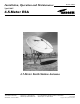
Installation, Operation and Maintenance Bulletin OM45T Revision F Type ES45T 4.5-Meter ESA 4.5-Meter Earth Station Antenna Andrew Corporation 10500 West 153rd Street Orland Park, IL U.S.A. 60462 Telephone: 708-349-3300 FAX (U.S.A.): 1-800-349-5444 Internet: http://www.andrew.com Customer Service, 24 hours: U.S.A. • Canada • Mexico: 1-800-255-1479 U.K.
Table of Contents Introduction Introduction . . . . . . . . . . . . . . . . . . . . . . . . . . . . . . . . . . . . . . . . . . . . . . . . . . . . . . . . . . . . . . . . . . . . . . . . 3 Proprietary Data . . . . . . . . . . . . . . . . . . . . . . . . . . . . . . . . . . . . . . . . . . . . . . . . . . . . . . . . . . . . . . . . . . . . 4 Information and Assistance . . . . . . . . . . . . . . . . . . . . . . . . . . . . . . . . . . . . . . . . . . . . . . . . . . . . . . . . . . . . 4 Notice . . . . .
Introduction Like all Andrew earth station antennas, the 4.5-meter earth station antenna provides high gain and exceptional pattern characteristics. The electrical performance and exceptional versatility provides the ability to configure the antenna with your choice of transmit/receive as well as receive-only, and for either linearly- or circularly-polarized C-Band, linearly-polarized Ku-Band, Hybrid C-/Ku-Band or X-Band operation.
Proprietary Data Information and Assistance Notice The technical data contained herein is proprietary to Andrew Corporation. It is intended for use in installation, operation, and maintenance of Andrew equipment. This data shall not be disclosed or duplicated in whole or in part without express written consent of Andrew Corporation. Andrew corporation provides a world-wide technical support network. The installation, maintenance, or removal of antenna systems requires qualified, experienced personnel.
How to Use This Manual Overview The scope of this manual is intended to provide station personnel with the base installation (ie: mount, reflector and enclosure), operation and maintenance requirements necessary for a 4.5-Meter Earth Station Antenna. Note: All antenna option instructions are included in the individual kit shipped with the part.
Getting Started Overview The installation, operation and maintenance of the 4.5-Meter Earth Station Antenna requires qualified personnel. Andrew installation, operation and maintenance instructions are illustrated for such personnel. Additionally, the antenna should be inspected by qualified personnel to verify proper installation, maintenance and condition of equipment as described in Preventative Maintenance.
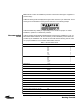
Note: Failure to follow an installation procedure could result in damage to equipment or personal injury. Additional warnings will be displayed throughout this manual for your awareness. These warnings can be identified in warning boxes as shown in the following sample. Andrew disclaims any liability or responsibility for the results of improper or unsafe installation, operation or maintenance practices.
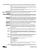
Parts Verification Upon receipt of your order, the shipment should be verified to ensure that all parts have reached your site. This process should occur before the installation process begins. Andrew Corporation thoroughly inspects and carefully packs all equipment before shipment. If you find that there are missing components, please refer to step-by-step instructions on how to properly report the equipment loss.
Installation Sequence Checklist The 4.5-Meter Earth Station Antenna requires the installation team to perform the assembly in the sequence presented below. Moreover, this sequence should be reviewed beforehand to ensure a smooth installation. Use the following checklist to verify and/or determine the installation sequence. Throughout the checklist certain part numbers will be used. Those part numbers describe the antenna currently being installed. The ES45T-R is a receive-only 4.
Tripod Ground Mount Assembly Mount azimuth axis support and rear anchor pads Connect support angles Attach support and elevation pivot assembly to support angles Attach support angles to azimuth axis joint Hoist support and pivot elevation pivot assembly Fasten azimuth axis joints to azimuth axis support Attach elevation strut to azimuth axis joint Attach azimuth strut to appropriate rear pad ES45T-T Main Reflector Assembly Remove protective covering from crate
Installation Procedures Overview This section provides installation procedures for the 4.5-Meter Andrew Earth Station Antenna. The installation procedures include instructions on the following antenna components. • • • • • • Mount Reflector Back Structure Reflector To Mount Assembly Subreflector Feed System Note: All installation instructions for the antenna options are contained in the parts kit included in the shipment.
A-325 Tensioning During the installation process there are several references to the A-325 hardware tensioning procedure. The A-325 hardware must be properly tensioned to avoid slippage between bolted surfaces under high loads. Slippage can cause the corresponding assembly to move, causing antenna misalignment. When designated, the A-325 hardware should be tightened according to the following tensioning procedure. Note: Tensioned bolts are for final connections only and should not be loosened for reuse.
Tripod Mount The three-point mount in an elevation-over-azimuth configuration optimized for geostationary satellite applications. The mount enables standard elevation ranges from 2°-62°, and 33°-90° with high-look strut configuration. Azimuth range is ±82°. Fine adjustment is provided in both azimuth and elevation. An example of the assembled tripod mount is provided in Figure 2. Figure 2 Before assembling the mount, verify that all parts are present.
300747 300747 Figure 4 Step 2 Loosely connect support angles (P/N 49624) with spacers (P/N 46560-2) to azimuth axis support and rear anchor pads as shown in figure 5. • Use A-325 ½ x 1-½ in. bolts and nuts for connections.
Step 3 Lay out support and elevation pivot assembly (P/N 49635) and support angles (P/N 49623) as shown in Figure 6. Figure 6 Step 4 Loosely bolt support and elevation pivot assembly (P/N 49635) and support angles (P/N 49623) to connection plates as shown in Figure 7. • • Use A-325 ½ x 1-½ in. bolts and nuts.
Step 5 Loosely attach support angles (P/N 49622) to the upper azimuth axis joint (P/N 300748) and the connection plates (part of P/N 49635)as shown in Figure 8. • • • Use A-325 ½ x 1-½ in. bolts, flatwashers and nuts.
Step 7 Tightly knot 40 ft. rope to azimuth axis joint (P/N 300748) for hoisting to azimuth axis support (P/N 49634). Figure 10 Step 8 Station one installer on a ladder to hoist support assembly as at least one other installer walks the assembly into the upright position as shown in Figure 10. Step 9 Loosely fasten lower azimuth axis joint (P/N 300746) and upper azimuth axis joint (P/N 300748) to azimuth axis support (P/N 49634) as demonstrated in Figure 11.
Step 10 Use a carpenter’s level to level support assembly as indicated in Figure 12. Loosen Ubolts to move support assembly up or down as needed to achieve level surface. Figure 12 Step 11 Tighten anchor bolts on rear pads and azimuth axis support base plate down using A325 procedure. See A-325 procedure for technique. (see page 12) Step 12 Loosely attach elevation strut (P/N 49766) to azimuth axis joint (P/N 300746) as shown in Figures 13 and 14. • Use ¾ x 3-½ in.
Figure 14 Step 13 Determine required length of elevation strut to nearest degree increment of desired elevation setting as specified in the Elevation and Azimuth Adjustments Section. Adjust coarse setting by extending secondary and, if necessary, tertiary sections to length. Install eight ½ in. set screws and securely tighten as pictured in Figure 15. CAUTION: Do not extend secondary or tertiary struts into red warning areas.
Step 14 Loosely attach azimuth strut end bracket (P/N 49767) to universal block (P/N 49705) as shown in Figure 16. • Use ¾ x 1-¼ in. bolts, flatwashers and lockwashers Figure 16 Step 15 Loosely attach block to appropriate rear pad as based upon calculations in Appendix F to determine the mounting configuration of the azimuth strut shown in Figures 16 and 17. • Use ¾ x 5-½ in.
Step 16 Connect U-bracket (P/N 49704) to appropriate connection plate. • Use A-325 ½ x 1-½ in. bolts, flatwashers and nuts. (see page 12) Figure 18 Step 17 Determine required length of azimuth strut to nearest degree increment of desired azimuth setting as specified in the Elevation and Azimuth Adjustments Section. Adjust azimuth setting by withdrawing secondary strut to achieve necessary length. Install four ½ in. set screws and securely tighten as demonstrated in Figure 19.
ES45T-R Reflector Assembly ES45T-R Reflector The ES45T-R-1 reflector is composed of six precision-formed panels designed for accuracy and strength and ensure reliable surface contour which provides exceptional operating characteristics in C- or Ku-frequency band. Step 1 Reflector should be assembled on a clear, flat area in front of the foundation pad. Clear debris from area and place plastic sheeting from packing crate as shown in Figure 22.
ES45T-R Reflector Assembly Note: All six reflector segments are identified individually by a two letter designation (AB, D-E, etc). Locate the markings on the reflector segments in order to assemble the reflector in the proper sequence. See Figure 21. Figure 21 Step 3 Place reflector segment A-B between two setting bands with concave side down as shown in Figure 22. Place reflector segment D-E opposite panel A-B.
ES45T-R Reflector Assembly Step 4 Raise segments and hold while loosely attaching mounting ring hub (P/N 49965) to convex side of center opening. • • Step 5 Use ¼-20 capscrews, lockwashers and nuts Insert capscrews from concave side of reflector segments Loosely attach reflector segments A-B and D-E to diameter setting bands (P/N 49426) with edge joining plates (P/N 49424) and capscrew hardware as shown in Figure 23.
ES45T-R Reflector Assembly Step 6 Loosely attach segment A-F to mounting ring hub, diameter setting bands and segment A-B using joining plates (P/N 49425) along reflector panel seam as pictured in Figure 24. • • Place spacers (P/N 200215) between first and third segments Insert ¼-20 capscrews from concave side of reflector segments Figure 24 Step 7 Loosely attach joining plate (P/N 49693) along A-A seam inside reflector rim as shown in Figure 25.
ES45T-R Reflector Assembly Step 8 Loosely attach segment E-F to mounting ring hub, diameter setting bands and segments A-F and D-E with joining plates (P/N 49425) along reflector panel seams E-E and F-F. Loosely attach joining plates (P/N 49693) on rim seams E-E and F-F as illustrated in Figure 26. Figure 26 Step 9 Station an installer inside reflector to finger-tighten seam hardware and attach final panels as pictured in Figure 27.
ES45T-R Reflector Assembly Step 10 Loosely attach reflector segment B-C to mounting ring hub and diameter setting bands. Use joining plates (P/N 49425) along B-B panel seam and joining plate (P/N 49693) on B-B rim seam. Step 11 Before last panel, lift reflector and return temporary supports to initial measuring position. Have installer inside reflector ensure setting bands are uniformly taut at this point.
ES45T-R Reflector Assembly Step 12 Install last reflector panel (C-D) by loosely attaching to diameter setting bands and mounting ring hub. Loosely attach panel seam hardware as installer inside moves reflector segment to enable segment union. Step 13 Loosely attach retaining bar (P/N 49997) to mounting ring hub (P/N 202429). Loosely attach center plate (P/N 49964-2) to concave side of reflector.
ES45T-R Reflector Assembly Reflector Leveling Procedure Step 1 Position (6) temporary supports near panel seams exactly as shown in Figure 29. Note: Temporary supports should be large enough to adequately support the reflector and strong enough to easily support reflector weight without compressing. Step 2 Position theodolite, transit or laser level about 10 feet [3m] from outside perimeter of reflector (see Figure 30). Step 3 Level theodolite/transit/laser level.
ES45T-R Reflector Assembly Step 9 Shim each location as required to level the reflector (see Figure 31). Continue to measure around antenna again, recording the height of each location mea- Step 10 sured. As before, shim the low location points to be at the same elevation as the highest measured location. Step 11 Continue to measure, record, compare and shim any low temporary support location points until all (6) temporary location points are within 0.030 inches [0.75 mm] elevation from each other.
ES45T-R Reflector Assembly ES45T-R-1 Back Structure The back structure assembly attaches to the rear of the reflector. The back structure provides stability for the reflector and maintains the parabolic accuracy of the dish. An example of the assembled back structure is presented in Figure 33. Figure 33 Before assembling the back structure, verify that the appropriate parts are present. The following steps provide the procedure for the back structure assembly.
ES45T-R Reflector Assembly Step 1 Refer to back structure Figure 34 for positioning and orientation details. • Apply stick wax (P/N 200852) to A-325 bolt threads before installation to reduce friction.
ES45T-R Reflector Assembly Step 2 Loosely attach tee plates (P/N 202447) to points B, F and D on convex side of reflector as shown in Figure 35. • Use A-325 ½ x 1-¼ in. bolts, flatwashers and nuts. (see page 12). • Insert bolts from concave side of reflector Figure 35 Step 3 Loosely attach plates (P/N 49427) to points A, C and E on convex side of reflector. Loosely attach two support angles (P/N 49438) to each of six plates as shown in Figure 36. • Use A-325 ½ x 1-¼ in. bolts, flatwashers and nuts.
ES45T-R Reflector Assembly Step 4 Loosely attach support angles (P/N 49436) to three tee plates (P/N 202447) as shown in Figure 37. • Use A-325 ½ x 1-¼ in. bolts, flatwashers and nuts. (see page 12) • Install bolts from concave side of reflector • Angles should be installed with edge in and flat side away from reflector as shown.
ES45T-R Reflector Assembly Step 6 Loosely attach support angles (P/N 49438) from plates A and C to angle (P/N 49436) from tee plate B with pivot bracket (P/N 300745). Step 7 Loosely connect support angles (P/N 49438) from plates E and C to angle (P/N 49436) from tee plate D to elevation axis bracket (P/N 300749) as shown in Figure 39. Figure 39 Step 8 Loosely connect pivot brackets and elevation axis bracket with the three support angles (P/N 49437) as pictured in Figure 40.
ES45T-R Reflector Assembly Reflector-to-Mount Assembly (With Crane) This reflector can be installed on the mount manually or by using a crane. However, Andrew recommends that this procedure be performed using a crane. The following steps provide the procedure for installing the reflector to the mount using a crane. Step 1 Ensure all connections on reflector and back structure are tight. Step 2 Wrap crane straps around support angle between pivot brackets as illustrated by Figure 41.
ES45T-R Reflector Assembly Step 3 Crane should place reflector so that pivot brackets align with support and elevation pivot assembly as shown in Figure 42. Figure 42 Step 4 Attach pivot brackets to support and elevation pivot assembly with U-bolts (P/N 995665), ½ in. lockwashers and ½-13 hex nuts as shown in Figures 43 and 44.
ES45T-R Reflector Assembly Figure 44 Step 5 Figure 45 Manually raise reflector to attach remaining end of elevation strut to elevation axis bracket of main triangle assembly as shown in Figures 45 and 46. • Use ¾ x 4-½ in. bolt, lockwasher and nut Figure 46 You have now completed the attachment of the reflector to the tripod ground mount assembly. If assembling a ES45T-R antenna, proceed to the Elevation and Azimuth Adjustments section for instructions on aiming your antenna at its desired satellite.
ES45T-R Reflector Assembly Reflector-to-Mount Assembly (With Hoist Kit) Step 1 The optional hoist kit (P/N 49080) must be assembled prior to reflector/ backstructure assembly hoisting. Hoist assembly should not be used for antenna elevation angle adjustment. The following steps provide the procedure for installing the reflector with the hoist kit. Install support tab assembly (P/N 49067) into top of azimuth axis support (P/N 49634) as shown in Figure 47.
ES45T-R Reflector Assembly Step 7 Loosely attach support (P/N 49060) and remaining ends of supports (P/N 49061) to corresponding pick-up assemblies (P/N 49064) using appropriate hardware (P/N 45980-1). Securely tighten all mounting hardware. • Ensure entire hoist assembly is centered on support and elevation pivot assembly (P/N 49635) Step 8 Securely attach winch assembly (P/N 39532) to lower portion of azimuth axis support (P/N 49634) using supplied U-bolts, lockwashers and nuts as shown in Figure 48.
ES45T-R Reflector Assembly Step 11 Remove small portion of foam padding from reflector packing crate and install under bottom portion of reflector assembly to prevent reflector damage during hoisting procedure. Position man at bottom of reflector/backstructure to guide assembly during hoisting procedure.
ES45T-R Reflector Assembly Step 14 Raise lower portion of reflector/backstructure assembly and attach remaining end of elevation strut to elevation axis bracket of main triangle assembly. • Use 3/4 x 4-1/2 in (114 mm) bolt, lockwasher and nut • Mechanical means or fine adjustment assembly may be utilized to achieve elevation angles greater than 30°. Step 15 Set fine elevation and azimuth strut positions based on the procedure performed in the Elevation and Azimuth Adjustments section.
ES45T-R Reflector Assembly Elevation and Azimuth Adjustments Step 1 Proper antenna pointing requires specific coarse and fine elevation and azimuth strut length adjustments which can be determined using the graphs provided in Appendix F. Adjustable azimuth and elevation struts are initially set in coarse setting as near as possible to pre-determined lengths. Fine elevation and azimuth settings are accomplished with threaded rod on elevation and azimuth struts.
ES45T-R Reflector Assembly Step 8 Fine Adjustment. Attach fine adjustment assembly between adjacent elevation strut sections as shown in Figure 50 using appropriate brackets, U-bolts, brass hex nuts, flatwashers and threaded rod. Securely tighten all adjustment assembly hardware. Note: Adjustment assembly may also be attached in alternate position shown depending on required elevation angle.
Feed Support Assembly By now, you can see that your installation of the 4.5-Meter Earth Station Antenna is almost complete. The feed system is the last phase of the base installation described in this manual. Note: All antenna options (such as feeds, shields, anti-icing, etc.) possess installation instructions within the individual kits contained in the shipment. Step 1 Attach feed struts to 222930 feed support as shown in Figures 52 and 53. • Use 3/8 x 2 in.
ES45T-T Reflector Assembly ES45T-T-1 Reflector The ES45T-T-1 reflector is composed of six precision-formed panels designed for accurate strength, and ensures a reliable surface contour that provides exceptional operating characteristics in C-, X- or Ku-frequency bands. Step 1 Reflector should be assembled on a clear, flat area in front of the foundation pad. Clear debris from area and place plastic sheeting from packing crate as shown in Figure 56.
ES45T-T Reflector Assembly Note: All six reflector segments are identified individually by a two letter designation (AB, D-E, etc). Locate the markings on the reflector segments in order to assemble the reflector in the proper sequence. See Figure 55. Figure 55 Step 3 Place reflector segment A-B between two setting bands with concave side down as shown in Figure 56. Place reflector segment D-E opposite panel A-B.
ES45T-T Reflector Assembly Step 5 Loosely attach reflector segments A-B and D-E to diameter setting bands (P/N 49612) with edge joining plates (P/N 49424) and capscrew hardware as indicated in Figure 57.
ES45T-T Reflector Assembly Step 7 Loosely attach joining plate (P/N 49693) along A-A seam inside reflector rim as shown in Figure 58. Top Match Markings A A F F Capscrew Hardware C 49693 Joining Plate Rear View D Adjacent Reflector Segments Side View D Match Markings Foundation Pad Figure 58 Step 8 Loosely attach segment E-F to mounting ring hub, diameter setting bands, and segments A-F and D-E with joining plates (P/N 49424) on panel seams E-E and F-F.
ES45T-T Reflector Assembly Step 9 Station an installer inside reflector to finger-tighten seam hardware and attach final panels as shown in Figure 59. Figure 59 Step 10 Loosely attach reflector segment B-C to mounting ring hub and diameter setting bands. Use edge joining plate (P/N 49424) on B-B panel seam and joining plate (P/N 49693) on B-B rim seam. Step 11 Before attaching last panel, lift reflector and return temporary supports to initial measuring position.
ES45T-T Reflector Assembly Step 12 Install final reflector panel (C-D) by loosely attaching to diameter setting bands and mounting ring hub. Loosely attach panel seam hardware as installer inside moves reflector segment to enable segment union. Step 13 Begin attaching corresponding reflector rib segments at match-marked position A-A using reflector segment seam hardware.
ES45T-T Reflector Assembly Step 2 Position theodolite, transit or laser level about 10 feet [3m] from outside perimeter of reflector (see Figure 62). Line of Sight (0.0° Elevation) Steel Rule 0.03-0.06 Inch Increment (0.5-1.0 mm) Theodolite, Transit or Laser Level Pointed Measuring Rod 6’ (1.8 m) Reflector Reflector Turn Back Diameter Setting Band Approx. 10 Feet (3 m) Shim Stack - Not Shown for Clarity Temporary Support 12 Inch (300 mm) Figure 62 Step 3 Level theodolite/transit/laser level.
ES45T-T Reflector Assembly Step 7 Position measuring rod point down over temporary supports and on the flat portion of the aperture face as shown in Figures 62 and 63, using theodolite/transit/laser level carefully measure and record relative height of each of the (6) temporary support locations. Note: Measuring rod must be held in a vertical position during all measurements. Step 8 From the recorded data determine the relative height of each of the locations as compared to the highest measured location.
ES45T-T Reflector Assembly Step 2 Feed Strut Assembly Step 1 Position white surface of center pad toward feed window and attach pad to center plate using supplied ¼ x 1-½ in. nylon screw, flatwashers and nuts. Install flatwashers under both screw head and corresponding nut as shown in Figure 64. Tighten mounting hardware allowing only slight compression (0.060” max.) of center pad material. Use remaining nylon nuts as locknuts and distort excess screw thread to prevent disassembly.
ES45T-T Reflector Assembly ES45T-T-1 Back Structure The back structure assembly attached to the rear of the reflector. The back structure provides stability for the reflector and maintains the parabolic accuracy of the dish. Before assembling the back structure, verify that the appropriate parts are present. The following steps provide the procedure for the back structure assembly.
ES45T-T Reflector Assembly Step 2 Loosely attach tee plates (P/N 202447) and corresponding rib connecting plates (P/N 202444) to points B, C, D, E, and F. • Use A-325 ½ x 1-¼ in. bolts, flatwashers and nuts. (see page 12) • Insert bolts from concave side of reflector CAUTION: Do not install A-325 ½ x 1-¼ in. hardware in center hole of rib connecting plates (P/N 202444) at positions B, D, or F only. Step 3 Loosely assemble two support angles (P/N 49438) to pivot bracket (P/N 300758).
ES45T-T Reflector Assembly Step 11 Check diameter setting bands to ensure they are uniformly taut. If not, check leveling of temporary supports and make necessary adjustments by adding or subtracting shims until bands are uniformly taut. Step 12 Begin A-325 hardware tensioning sequence (see page 12) with tee plates (P/N 202447) and rib connecting plates (P/N 202444). Next tighten support angle (P/N 49436) connections. Tighten the pivot brackets and elevation axis bracket last.
ES45T-T Reflector Assembly Step 3 Crane should place reflector so that pivot brackets align with support and elevation pivot assembly as shown in Figure 68. Figure 68 Step 4 Attach pivot brackets to support and elevation pivot assembly with U-bolts (P/N 995665), ½ in. lockwashers and ½-13 hex nuts as shown in Figures 69 and 70.
ES45T-T Reflector Assembly Figure 71 Figure 70 Step 5 Attach remaining end of elevation strut to elevation axis bracket of main triangle assembly as shown in Figures 71 and 72. • Use ¾ x 4-½ in. bolt, lockwasher and nut Figure 72 You have now completed the attachment of the reflector to the tripod ground mount assembly. Proceed to the Elevation and Azimuth Adjustments section for instructions on pointing your antenna towards the desired satellite.
ES45T-T Reflector Assembly Reflector-ToMount Assembly (With Hoist Kit) Step 1 The optional hoist kit (P/N 49080) must be assembled prior to reflector/ backstructure assembly hoisting. Hoist assembly should not be used for antenna elevation angle adjustment. The following steps provide the procedure for installing the reflector with the hoist kit. Install support tab assembly (P/N 49067) into top of azimuth axis support (P/N 49634) as shown in Figure 73.
ES45T-T Reflector Assembly Step 8 Securely attach winch assembly (P/N 39532) to lower portion of azimuth axis support (P/N 49634) using supplied U-bolts, lockwashers and nuts as shown in Figure 74. • Keep winch cable aligned with sheaves Figure 74 Step 9 Step 10 Begin releasing winch cable. Route cable through both sheaves allowing sufficient cable length to reach top of main triangle assembly on reflector backstructure.
ES45T-T Reflector Assembly Step 12 Hoist reflector/backstructure assembly to vertical position until upper joints of main triangle assembly contact pipe and straddle two locator bars on support and elevation assembly (P/N 49635) as shown in Figure 75. Figure 75 Step 13 Install two U-bolts at each pivot bracket of main triangle assembly. • Use 1/2 inch (13 mm) lockwashers and nuts.
ES45T-T Reflector Assembly Step 15 Set fine elevation and azimuth strut positions based on the procedure performed in the Elevation and Azimuth Adjustment section. • If fine alignment is not performed at this time, continue the assembly procedure at Step 16. Step 16 Securely tighten U-bolts and elevation strut mounting hardware. Step 17 Remove both fine adjustment assemblies and store in a weather protected location for future use. Continue with feed system and corresponding LNA installation.
ES45T-T Reflector Assembly Step 6 Determine required length of azimuth strut to nearest degree increment of desired azimuth setting. Adjust coarse azimuth setting by withdrawing secondary strut section from primary strut to achieve desired strut length. Install four 1/2 inch (13 mm) set screws in holes provided and securely tighten. Note: Do not extend secondary strut section into red warning area.
Step 10 Set fine elevation and azimuth strut positions by loosening strut set screws and selected out fine adjustment hex nut. Turn corresponding inner hex nut in appropriate direction until required strut length is achieved. Securely tighten strut set screws and corresponding outer hex nut. Step 11 During final electrical tuning, adjust elevation and azimuth struts appropriately to lengthen or shorten struts for optimal signal strength.
Polarization Adjustment Step 1 Connect receive LNA output to spectrum analyzer and fine adjust elevation and azimuth strut lengths to achieve maximum signal strength from desired satellite. Step 2 Loosen four 3/8 x ½ in. set screws in feed support until feed assembly is free to rotate and adjust feed for maximum receive signal strength on desire polarization. Note: Do not loosen collar hardware (P/N 49795).
Medium Modular Mount Refer to bulletin 237151C, for Installation Instructions.
Operation Overview Acquiring A Satellite Step 1 After you have completed the assembly of your antenna, you are now ready for it to become operational. In order to operate the earth station antenna, you will need to direct it to the desired satellite adjusting both the elevation and azimuth angles appropriately. The following procedures provide details on how to correctly position your antenna on the desired satellite.
While viewing the spectrum analyzer screen, a pure noise signal as shown in Figure 1 will probably be observed. Additionally, some transponder signals may be observed above the noise signal as shown in Figure 2. Figure 1 Figure 2 The following steps provide the procedure for acquiring a satellite. Step 1 Manually move the antenna in the azimuth (scanning back-and-forth) to achieve the maximum (greatest amplitude) transponder signals.
The maximum azimuth excursion from the original setting should not exceed ±1.5° or the antenna may begin to access a different satellite. Step 2 With the antenna positioned in azimuth such that the transponder signals are maximized, follow the same procedure manually moving the antenna in elevation (scanning up-and-down) to further maximize the transponder signals.
Step 6 Move the antenna in elevation while observing the spectrum analyzer screen. If the signal amplitude increases, decreases and then increases again but to a lesser value, the antenna is moving in the wrong direction; reverse the direction of the antenna movement. From the original null point, the signal level should decrease and increase alternately, but with an increasing amplitude until the transponder signal increases to a level of at least 30 dB.
Figure 5 Figure 6 Manual Actuator Assembly Removal After you have successfully acquired the satellite and all adjustments have been made, the manual actuator should be removed. The following steps provide the procedure for the proper removal of the manual actuator assembly. Step 1 Remove the manual actuator assembly by first removing the hardware securing the actuator to the base angle. Note: The adjustment kit assembly should be removed after the antenna has been adjusted.
Preventive Maintenance Overview This section contains periodic preventative maintenance instructions for the 4.5-Meter Earth Station Antenna. Included in this section are inspection and preventative maintenance procedures including cleaning and lubrication, painting and an operational voltage/current checkout procedure deemed within the capabilities of the average station technician.
Mechanical Parts scraper, stiff brush (bristle, or wire in the case of rust or corrosion), or cloth or compressed air at 25 to 40 psi. Any accumulated imbedded dirt, corrosion, grease or oil deposits that require further cleaning may be removed with a bristle or wire brush and a cleaning solvent such as trichlorethylene or equal. After cleaning, allow cleaned parts to dry for 10 to 15 minutes before placing the equipment into operation.
• Check all electrical components for dirt, chips, cracks, breaks, discoloration or other signs of deterioration and damage. A discolored, blistered or burnt condition is evidence of overload. Measure actual value of suspect electrical components and compare against specified value where applicable. • Check transformer for an excessive wax deposit on the surface, discoloration or a pungent odor indicative of burning varnish denoting overheating or a total breakdown.
• Check all electrical components for dirt, cracks, chips, breaks, discoloration and other signs of deterioration and damage. A discolored, blistered or burnt condition is evidence of overload. • Operate the azimuth and elevation drives as well as the feed rotation in both the plus and minus direction from the local control/motor drive controller at least once every three months during antenna down time.
• Check security of antenna mounting and interconnecting assembly hardware. Be certain all electrical grounding connections (including cross-axis grounding straps) and intact and secure, not corroded or broken. Thoroughly clean any noticeable corroded portions of grounding cables, unplated portion of universal terminals and corresponding mounting surfaces with a wire brush. Replace rather than tighten any loose A-325 structural hardware.
Step 5 Turn the ELEVATION DOWN/UP switch to either position and while the antenna is rotating, carefully use a clamp-on ammeter in accordance with the ammeter manufacturer’s instructions to take current readings off each of the power conductors (phases) connected to the main terminal block at the bottom of the panel. Record the current draw in the equipment log and compare the readings to the reference values entered in the installation/acceptance check-off.
Preservation of Component Parts Aluminum Parts When preserving component parts, refer to the following paragraphs in this section. Remove all loose paint and corrosion by scraping, wire brushing or using steel wool. If using steel wool near the feed window, make sure that none remains on the feed horn window. Edges of existing paint can be blended with a metal surface by using a fine grit sandpaper. Wipe the surface to be painted with a soft rag dampened in trichlorethylene, lacquer thinner or equal.
the application of lubricant to any parts, use a clean cloth and/or bristle brush and remove any old lubricant to prevent an excessive build-up. Remove indicated access plugs from square tube weldment and apply lubricant to panning frame tube assembly and corresponding thrust pads. Securely replace access plugs in square tube weldment. Be certain to remove any protective caps and clean off each lubrication fitting prior to injecting fresh grease.
Table 1.