
User Manual


Andrew InCell™ Fiber Optic Distributed Antenna System Users Guide
- iii -
List of Tables
Table 1. InCell™ Performance Specification............................................................................17
Table 2. BTS Interface Specifications ......................................................................................18
Table 3. Antenna Interface Specifications ................................................................................19
Table 4. Electrical Specifications .............................................................................................19
Table 5. InCell™ Environmental and Mechanical Specification...............................................20
List of Figures
Figure 1. InCell™......................................................................................................................1
Figure 2. InCell™ Form Factors ................................................................................................1
Figure 3. Andrew Dual Band Patch Antenna..............................................................................5
Figure 4. Andrew Dual Band Omni Antenna...............................................................................5
Figure 5. Simplified InCell™ Block Diagram ............................................................................7
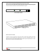
Figure 6. InCell™ Central Distribution Unit ..............................................................................1
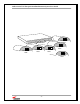
Figure 8. Remote Antenna Unit..................................................................................................8
Figure 9. System expandability to 48 RAUs...............................................................................9
Figure 10. System Expandability to more than 48 RAUs..........................................................10
Figure 11. Cross Section of Andrew Composite Fiber/Copper Cable........................................11
Figure 12. Remote and Local Power Connections on the RAU.................................................12
Figure 13. Typical System Configuration Using Off-Air Interface............................................16
Figure 15. Remote Alarm Capability........................................................................................23
Figure 16. Daisy Chaining CDU’s for Remote Monitoring.......................................................23