
User Manual


Users Guide - Andrew InCell™ Fiber Optic Distributed Antenna System
1-10
Downlink Signal Flow
The downlink signal is the signal that is transmitted from the base station and received by the
mobile phone. In the InCell™ Fiber Optic Distributed Antenna System, the CDU receives the
downlink RF signal from a base station, converts the signal into six identical optical signals and
distributes the optical signals to ERAUs that are located throughout a building. The ERAU
receives the optical downlink signal and converts it back to an RF signal, which is then broadcast
to mobile phones located within the building.
If the InCell system is connected directly to indoor base station equipment, the downlink is
supplied to the CDU via a coax cable to the base station. If the InCell system uses an off-air
antenna and repeater to interface to an external base station, the RF downlink signal is
transmitted through the air, received by an off-air donor antenna and amplified using a bi-
directional amplifier prior to entering the CDU.
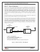
The wireless downlink signal is received through the Type N connector on the rear panel of the
CDU and is split into six identical RF signals, one for each port of the CDU. A laser diode at
each CDU port converts the RF signal into an optical signal. The optical signal for each CDU
port is transmitted through the D/L fiber optic bulkhead connector, through a single mode fiber
optic cable to the D/L fiber optic bulkhead connector on the ERAU.
The ERAU converts the optical downlink signal back to an RF signal using a photodiode. The
RF downlink signal is amplified, filtered and then passed through the ERAU Type N connector
to a directional or omni antenna where it is transmitted to the mobile phone.
Uplink Signal Flow
The uplink signal is the signal that is transmitted from the mobile phone and received by the base
station. In the InCell system, an indoor antenna receives the uplink RF signal from the mobile
phone and passes the uplink signal to the ERAU through the Type N connector located on the
rear panel of the ERAU. The ERAU amplifies and filters the uplink RF signal and then converts
the RF signal into an optical signal using a laser diode. The optical signal passes through the
U/L fiber optic bulkhead connector, through a single mode fiber optic cable to the U/L fiber
optic bulkhead connector on the CDU.
The CDU converts the received optical uplink signal back to an RF signal with a photodiode.
The uplink signals from each of the six remote antennas are received by the six CDU ports and
are combined together to pass through the Type N RF connector on the back of the CDU and
then up to the base station.