
User Manual


Users Guide - Andrew InCell™ Fiber Optic Distributed Antenna System
1-9
InCell Theory of Operation
Since no two indoor coverage requirements are the same, in-building RF coverage solutions may
involve one or a combination of RF coverage methods. Andrew can provide several solutions to
optimize the indoor RF coverage for a wide range of indoor applications. The InCell™ Fiber
Optic DAS complements other Andrew in-building RF coverage methods such as passive and
active leaky feeder RF distribution networks using Radiax cable, passive distributed antenna
systems and active distributed antenna systems. In-building wireless systems are typically
connected to an off-air donor antenna and repeater or to a BTS system located within the
building.
The InCell™ DAS uses low loss single mode fiber optic cables to distribute the uplink and
downlink signals throughout buildings or between multiple buildings.
The InCell system uses direct analog modulation of the RF signal onto the optical signal through
a laser diode. The modulated optical signal from the laser travels over the fiber optic cable to a
photo diode, which converts the optical signal back to an electrical signal. There is no frequency
conversion (mixing the signal up and down to an IF frequency). Because of the direct RF to
optical conversion, the InCell system is technology transparent, easily passing analog, TDMA,
CDMA and 3G type signals.
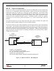
RF
Up to 6 RAUs
Remote
Antenna Unit
(RAU)
- 1 system -- up to 6 antennas
- 1 main hub x 6 antennas = 6 antennas
- D/L + U/L: Direct RF to optical to RF conversion
- Typically only 1 antenna per RAU
- No long coax cables needed—resulting in improved coverage area
D/L
U/L
E
O
Central
Distribution Unit
(CDU)
O
E
DUPL
Coax
Single Mode Fiber
Figure 1-3. High Level InCell Block Diagram