
User guide

Bulletin II-102051-EN • Revision B November-2007 9
-(
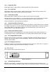
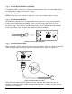
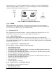
The Power Cable is illustrated in Figure 7. Two color-coded or number-coded 18 – 24 AWG wires in
a common jacket are attached to a pluggable terminal block on one end for connection to the PDU.
The opposite end is unterminated.
Power Cables are available in a selection of lengths and can be trimmed to the desired length on
site.
Figure 7: Power Cable
. "(
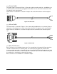
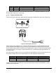
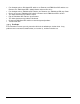
The Alarm Cable is illustrated in Figure 8. Three color-coded 24 AWG wires in a common jacket are
attached to a D-sub plug on one end for connection to the PDU. The opposite end is unterminated.
Alarm Cables are available in a selection of lengths and can be trimmed to the desired length on
site.
Figure 8: Alarm Cable
/ ,0%
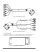
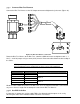
Bias Tee Harnesses are available in two styles. The standard style is illustrated in Figure 9 and has
six RG174 coaxial cables in a common jacket. The sector-split style (Figure 10) features three
jackets, each with two cables. A single D-sub plug connects to the PDU while the opposite end splits
to six SMA-male connectors to mate with Bias Tees. Individual cables are color-coded and may also
be numbered 1-6, matching the numbered PDU outputs:
Bias Tee Harnesses are available in a selection of lengths.