
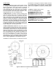
Specifications

1.4 Raise reflector to approximately 15° elevation angle
using supplied handwheel on elevation jack.
1.5 Slowly swing the reflector sides out into their operating
position and lock in place with the two lower 1/2-turn fas-
teners on each side.
Note: Ensure alignment pins properly aligned.
1.6 Lower the reflector and lock up the remaining 1/2-turn
fasteners to lock the reflector `wing’ panels to main reflec-
tor.
1.7 Referencing the following photographs and drawing
239351, remove feed support yoke from stowed location
and using a ladder, carefully climb into the reflector and
assemble the feed support struts.
1.0 Normal System Set-Up Procedure
WARNING: Extreme care must be taken during the fol-
lowing system set-up and stowing procedures to avoid
bodily injury and/or equipment damage.
1.1 Choose a site which is as level as possible with the rear of
trailer facing as closely as possible in the direction of the satel-
lite.
Note: The reflector has a maximum of ±135° azimuth ad-
Justment but set-up time and antenna stability can be im-
proved by this positioning of trailer.
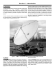
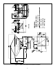
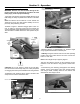
1.2 Refer to Figure 4. Release outrigger jacks at four cor-
ners of trailer by removing locking pins ard reinsert into
closest applicable height adjustment holes to lock in place.
Jack the trailor to a stable and close to level position as pos-
sible.
Figure 4. Outrigger Jack Extension
CAUTION: Do not use fingers to assist in pin hole align-
ment and ensure feet are kept away from under pad portion
of outrigger jacks when jack assemblies are being lowered.
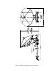
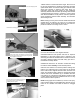
1.3 Release both elevation safety clamps, elevation strut
clamp and four reflector hold-down bolts.
Section 2 - Operation
Height
Adjustments
Holes
Outrigger
Jack
Locking
Pins
Outrigger
Jack
Assembly
9
Elevation Safety Clamps (2)
Do not loosen these
screws (3)
Elevation Strut Clamp - must be loose prior
to raising/lowering reflector
Reflector Hold-down Bolt Assemblies (4)
Remove Feed Support Yoke from stowed location