
Specifications


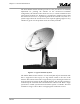

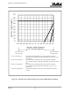

Table of Contents
42S315F v
LIST OF FIGURES
Figure 1-1. Typical Antenna System....................................................................................................1-2
Figure 1-2. Elevation and Azimuth Angle Stow Chart for High Wind Conditions .....................1-4
Figure 2-1. 9-Meter Antenna Reflector and Subreflector Alignment............................................2-18
Figure 2-2 Installing Leveling Nuts..................................................................................................2-21
Figure 2-3 Rigging Lifting Points......................................................................................................2-25
Figure 2-4 Rigging Lifting Points......................................................................................................2-28
Figure 2-5. Hoisting Reflector and Spars ..........................................................................................2-34
Figure 2-6. Hoisting Feed....................................................................................................................2-36
Figure 3-1. Feed, Reflector, and Subreflector Distances ...................................................................3-3
Figure 3-2. Typical Antenna Patterns for Various Subreflector Position .......................................3-6
Figure 4-1. Lubrication Points (Sheet 1 of 2) ......................................................................................4-4
LIST OF TABLES
Table 1-1. Antenna Mount Configurations.........................................................................................1-1
Table 2-1. Tools and Equipment Required For Installation ..............................................................2-5
Table 2-2. Torque Values For Antenna Fasteners..............................................................................2-7
Table 2-3. Panel Rough Alignment....................................................................................................2-15
Table 2-4. Final Alignment Target Measurements - Sight Center of the Middle Diamond ......2-17
Table 2-5. 9-Meter Reflector Alignment Record ...............................................................................2-19
Table 4-1. Torque Values For Antenna Fasteners............................................................................4-10
Table 5-1. Drawing Index......................................................................................................................5-1