
User Manual

2.0 Equipment Description
1.2 Physical Configuration
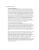
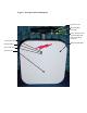
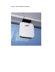
Figure 1 is an illustration of the PCS-1900-xx “Propagator” Repeater (hereafter
referred to as the SSR) indicating important features. As shown in the illustration
there is a main electronics housing (chassis) that has a square shape with rounded
corners. The chassis is attached to a mounting base that incorporates an azimuth
rotation feature with detents. The approximate size of the chassis is 15” X 15” X 4”;
the corners have a 3” radius. The mounting bracket has a base that is approximately
9” X 3.75” X 0.75” that positions the chassis approximately 3.25” away from its
mounting surface. The unit weighs approximately 8.75 pounds without the power
supply. A separate, AC wall outlet mounted, DC power source is provided. This unit
is approximately 3.75” X 2” X 1.25” in size and weighs approximately 0.8 lbs. A
white plastic radome covers each 15” X 15” face of the chassis; these surfaces are
electrically active and must be kept free of contaminating materials. Also, take
special note that each face of the SSR has a unique electrical function and must
properly oriented in operation (see section 2.0). The radome with the Andrew flash
indicates which side should be facing the handset (mobile unit).
1.3 Electronic Description & Block Diagram
The 1900 series PCS repeaters operate in the 1900 MHz PCS band. They were
developed to provide more reliable coverage and/or range extension of PCS systems
within sheltered structures. Three models cover all US PCS sub-bands (AD, BE,
& FC). Pre-aligned antennas on each side of the repeaters make them easy to install
and simple to operate. Designed for indoor environments, they only require a
standard US 110VAC outlet for operating power. The design employs high linearity
amplifiers that work well with all popular signal formats (TDMA, CDMA, GSM,
etc.).
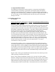
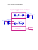
Figure 2 is an electronic block diagram of SSR internal and external circuitry. A full
band internal antenna on the base station face of the SSR (donor antenna) feeds a
highly selective diplexer functions to separate and isolate the uplink (Tx) and
downlink (Rx) signal paths. A different internal full band antenna and diplexer on
the mobile face of the SSR function in a complementary manner to separate and
isolate the uplink (Rx) and downlink (Tx) signal paths. The signal from each
diplexer’s Rx filter feeds an amplifier with an AGC loop that limits maximum output
power to approximately 4 milliwatts. The amplifier RF outputs feed the
complementary TX band pass filter in each diplexer which functions to limit spurious
amplifier output signals and further isolate the complementary band’s signal. Both
amplifiers include Received Signal Strength Indicator (RSSI) circuitry and over-
current protection circuitry.