
User Manual
the glass the 73 dB system (50 dB active) gain setting is recommended for maximum
stability margin.
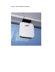
Figure 4 is the next best installation location: mounted on an interior wall surface of
typical gypsum wallboard (drywall) construction about 7 or 8 feet off the floor but not
too close to the ceiling. Be careful to position the SSR between metal studs in the
wall if present. Extensive stability testing has shown this mounting location to
provide stable operation for both gain settings of the SSR.
Figure 5 show a third acceptable installation location: mounted on the ceiling or on
extension poles of 1’ or 2’ lengths. The 73 dB system (50 dB active) gain setting has
been show to provide stable operation for all ceiling mount configurations. The 83
dB system (60 dB active) gain setting is only recommended for the 2’ extension pole
configuration. When using the extension pole configurations the SSR must be keep
well above floor level (at least 8’).
When mounted to a ceiling it may be desirable to point the Propagator in a different
direction. The mounting base has a built-in detent rotation feature that allows the
main electronics chassis to be rotated ± 47 degrees about its vertical axis. Simply pull
down on the mounted Propagator and rotate to a new detent position.
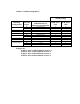
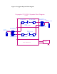
Table 1 summarizes the stability rating verses mounting location with gain setting as
a parameter.
2.2 Mounting Considerations
Mounting should be accomplished with due consideration of the minimization of
undesirable feedback signal discussed in section 2.1. The mounting base along with
its companion mounting plate provide for a wide variety of structural attachment
methods when installing the SSR. The polarization of the base station facing
antennas in the SSR strongly favors attachment of the mounting base to a horizontal
surface above or below the SSR. Standard fastening techniques can be used to attach
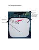
the aluminum mounting plate shown in Figure 6 to the desired horizontal surface.
Once the mounting plate is securely attached to the mounting surface the SSR is
attached to the threaded studs on the mounting plate using the provided nylon
thumbnuts (see Figure 7).
2.3 Power Supply Location & Connections
The power supply furnished with the SSR requires a standard US 110 VAC outlet. It
connects to the SSR via a permanently attached two-conductor cable. The location of
the power supply also requires special attention to the minimization of undesirable
feedback signals. The recommended location is as near the plane that bisects the SSR
around the finned edge as possible and as far away from the SSR as possible.