
User Manual

3.0 Operation Guide Lines
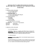
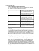
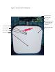
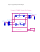
3.1 Status Indicating Light Emitting Diodes (LEDs)
Four small status indicating LEDs are visible on the Mobile unit facing side of the
SSR; they provide the following information (see Figure 1):
On state indicates that SSR is receiving power
from the power supply and the internal circuitry
has not exceeded the maximum safe current
demand.
Green LED nearest the mounting base.
Off state (concurrent with an off state for the
adjacent Red LED) indicates that the SSR is not
receiving power from the power supply.
On state indicates an internal over current event
has occurred. Power to the SSR must be
interrupted for 10 or more seconds to reset this
“circuit breaker” function. Repeated resets
(more than 3 times in 30 minutes) may cause
permanent damage to SSR.
Red LED adjacent to Green Power LED
described above.
Off state (with concurrent on state of power
LED) indicates normal SSR operation
Green LED adjacent to red LED described
above.
RSSI for the down link (signal received from
the base station and re-transmitted to the
handset). On state indicates reception of a
useable signal from the base station.
Green LED near the edge of the SSR opposite
the green Power described above.
RSSI for the up link (signal received from the
handset and re-transmitted to the base station).
On state indicates reception of a useable signal
from the handset.
3.2 Stability
After mounting the SSR in a location selected using the guidelines of section 2.0 and
connecting the power supply stable operation must be confirmed. If stable operation
in the selected location cannot be achieved, either another stable location must be
found. If the subject SSR is set at the 60 dB active gain level (83 dB system gain) it
may be possible to achieve stable operation by setting the gain of the SSR to the 50
dB active gain (73 dB system gain) state per the procedure described in Appendix C.
A good way to confirm stable operation is by use of a spectrum analyzer and a
suitable pick-up antenna. Locate the spectrum analyzer and pick-up antenna outside
the 15-20 feet clear field hemisphere of the SSR, adjust the analyzer controls to
display signals in a 150 MHz band centered on the operating band of the SSR (see
appendix A), and set the analyzer bandwidth, attenuation, and sweep parameters to
provide –90 to –100 dBm measurement sensitivity. Turn off the SSR by removing
its’ power cable. While viewing the analyzer display, turn the SSR back on and
watch for spurious signals that change amplitude and frequency in a random manner.
The presence of such randomly changing signals is a strong indication of an unstable
SSR. With a normally operating SSR you should be able to see the base station down
link signal and this signal should increase in amplitude when the SSR is turned on
(See Figure 7).