INSTALLATION GUIDE, OPERATION AND SERVICE MANUAL NATURAL GAS FIRED STORAGE WATER HEATERS HI-FLO RANGE Models 32/143, 65/173, 81/264, 62/341, 54/418, 54/440 Permanent Pilot, Auto Ignition with Flue Damper ‘E’/‘F’ Series STANDARD RANGE Models 24/39, 32/40, 40/61, 63/62, and 84/87 Permanent Pilot, Auto Ignition ‘G’ Series T H I S M A N U A L M U S T B E K E P T W I T H T H E A P P L I A N C E April 2007 Part No.
the nation’s favourite for PLUMBING & HEATING SUPPLIES FREE SHIPPING SECURE PAYMENTS on all orders over £100 to mainland UK shop online with confidence FINANCE AVAILABLE PRICE MATCH spread the cost with low interest rates always get the best deals available we have H U G E R E D U C T I O N S ON THOUSANDS OF ITEMS Boilers Bathroom suites Radiators Kitchen sinks & taps Heating controls Showers Pipes & ittings Wet rooms Cylinders Towel warmers Fires Bathroom furniture Renewable energy
© Copyright Andrews Water Heaters 2007 Reproduction of any information in this publication by any method is not permitted unless prior written approval has been obtained from Andrews Water Heaters. Andrews Storage Water Heaters have been designed and manufactured to comply with current International standards of safety. In the interests of the health and safety of personnel and the continued safe, reliable operation of the equipment, safe working practices must be employed at all times. The attention of U.
CONTENTS SECTION 1 SECTION 2 SECTION 3 SECTION 4 SECTION 5 SECTION 6 SECTION 7 SECTION 8 SECTION 9 PAGE GENERAL AND SAFETY INFORMATION General Information British Standards Health and Safety Regulations 1993 Legionellae in Water Heaters 2 2 3 3 TECHNICAL DATA Standard Range Hi-Flo Range 4 5 INSTALLATION Introduction Draught Diverter Location Gas Supply Electrical Supply Flue Systems Air Supply and Ventilation Water Quality and Treatment Water Connections- Hydrojet System Vented Systems, Stand
SECTION 1 GENERAL INFORMATION GENERAL AND SAFETY INFORMATION The Andrews Water Heater has been designed for use with NATURAL GAS only and is manufactured to give an efficient, reliable and long service life. To ensure the continued, trouble-free operation of your heater at maximum efficiency, it is essential that correct installation, commissioning, operation and service procedures are carried out strictly in accordance with the instructions given in this manual.
GENERAL AND SAFETY INFORMATION It is the duty of manufacturers and suppliers of products for use at work to ensure, so far as is practicable, that such products are safe and without risk to health when properly used and to make available to users, adequate information about their safe and proper operation. Andrews Water Heaters should only be used in the manner and purpose for which they were intended and in accordance with the instructions in this manual.
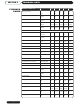
SECTION 2 STANDARD RANGE TECHNICAL DATA ANDREWS MODEL NO. 24/39 32/40 40/61 63/62 84/87 Storage Capacity l gal 109 24 145 32 182 40 286 63 382 84 Recovery thro' 44ºC/80ºF l/h gal/h 178 39 182 40 278 61 281 62 397 87 Recovery thro' 56ºC/100ºF l/h gal/h 142 31 146 32 220 49 227 50 316 70 Heat Input Gross kW Btu/h 12 12.5 19 19 26 40,944 42,650 65,000 65,000 88,712 Heat Input Net kW Btu/h 11 11.
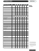
TECHNICAL DATA SECTION 2 ANDREWS MODEL NO. 32/143 65/173 81/264 62/341 54/418 54/440 Storage Capacity l gal 145 32 295* 65 368* 81 282* 62 245* 54 245 54 Recovery thro' 44ºC/80ºF l/h gal/h 649 143 786 173 1199 264 1549 341 1900 418 1998 440 Recovery thro' 56ºC/100ºF l/h gal/h 517 114 629* 138 959 212 1239* 273 1520* 334 1598* 352 Recovery thro' 72ºC/130ºF l/h gal/h 399 88 484* 106 730 162 953* 210 1169* 257 1223* 270 Heat Input Gross kW Btu/h 42.
SECTION 3 INTRODUCTION INSTALLATION THE LAW REQUIRES THAT INSTALLATION IS CARRIED OUT BY A PROPERLY QUALIFIED PERSON Installations must be carried out in accordance with Gas safety (Installation and Use) Regulations 1998, Building Regulations, The Water Supply (Water Fittings) Regulations 1999 and any requirements of the local Gas Authority, Local Authority, Water and Fire Authorities and the current British Standards and Codes of Practice listed in Section 1.
INSTALLATION SECTION 3 The heater must not be installed in any location which contains a bed, bath or shower. LOCATION There must be easy access to the boiler room and heater at all times. A clearance of 800mm (311⁄2 in) for Hi-Flo and 300mm for Standard Range should be left at the front of the heater for removal of the burner. Clearances at the sides and rear of the heater should be at least 305mm (12 in).
SECTION 3 INSTALLATION GAS SUPPLY Gas Supply Cock, Hi-Flo Models Fig 2. Fit the gas cock immediately upstream of the gas control valve using a suitable jointing compound and connect to the gas supply. An inlet nipple complete with pressure test point nipple is factory fitted to the gas control valve to avoid possible damage. Gas Valve Gas Cock Nipple BSP Thread U.P.T. Thread Fig 2.
INSTALLATION SECTION 3 Fig 3a. Standard Range G737LGA INTERMITTENT PILOT IGNITION CONTROL FLUE FAN INTERLOCK 24V REMOTE TIMER 24V INDEPENDENT MOTOR SUPPLY Fig 3b.
SECTION 3 FLUE SYSTEMS INSTALLATION Detailed recommendations for flue installation are given in BS 6644, BS5440 Pt 1 and British Gas publication IM/11 - Flues for Commercial and Industrial Gas Fired Boilers and Air Heaters. The flue connection is designed for BS 835 type heavy duty flue, but light quality flue pipe, mild steel or stainless steel sheet may be used using the appropriate adapter. Flue pipes etc. shall be fitted socket-up to keep any condensate within flue and appliance.
INSTALLATION SECTION 3 FLUE SYSTEMS 600mm* Split Flue Clip 1. This flue run must not be used Fig 4b. 2 & 3 are recommended flue runs *A minimum of 600mm of vertical flue directly above the draught diverter should be provided where possible on all natural draught flue installations. If this dimension cannot be achieved please contact Andrews Water Heaters. Please note this is not required where a common flue header is used on multiple installations. Fig 5.
SECTION 3 INSTALLATION Minimum Heights from Roof to Base of Flue Terminal Type of Roof Not within 1.5m (5ft) of a vertical surface of a structure & on the roof Internal Route On Ridge Pitch exceeding 45º Pitched Pitch not exceeding 45º At or above ridge level With parapet Not applicable Flat Without parapet AIR SUPPLY AND VENTILATION Not on Ridge External Route 1m (3.3 ft) above roof intersection 1m (3.
INSTALLATION IMPORTANT! 1. The effective area requirements specified in the table are related to the maximum net input of the heater(s) and are equivalent to those specified in BS 6644 and IGE/UP/10 Pt.1. SECTION 3 AIR SUPPLY AND VENTILATION 2. The free area of the grilles should not be less than the size of the recommended ventilation opening. 3. The supply of air to a space housing the heater(s) by mechanical means should be: (a) Mechanical inlet with natural extraction.
SECTION 3 WATER QUALITY AND TREATMENT INSTALLATION Where extreme conditions of water hardness exist, scale can form in any water heating equipment, especially when the heater is working under conditions of constant heavy demand and at high temperatures. Each water heater is fitted with one or more magnesium anode(s) which protect the tank from corrosion caused by electrolytic action. Magnesium anodes are sacrificial in that they corrode as they protect.
INSTALLATION SECTION 3 WATER CONNECTIONS Hydrojet System The upper “jet ports” direct the flow outward to begin the dynamic mixing action. The lower “jet ports” direct the flow inward to increase the turbulence. Tank Heater Casing All models now incorporate the new Mini Hydrojet system on cold inlet side connections. This system ensures water is directed onto the tank base which minimises sediment build up from day one of installation.
SECTION 3 WATER CONNECTIONS INSTALLATION VENTED SYSTEMS, STANDARD RANGE The water heater must be supplied from a cold water feed cistern and the hot water supply pipe must be fitted with an open vent pipe in accordance with BS 5546 and BS 6644. The Water Supply (Water Fittings) Regulations 1999 must be observed when installing the system.
INSTALLATION SECTION 3 Fig 6A. Fig 7.
SECTION 3 WATER CONNECTIONS INSTALLATION UNVENTED SYSTEMS, STANDARD RANGE Unvented Systems should be fitted by an Approved Installer When used in an unvented system, the Andrews Water Heater will supply hot water at a pressure of 3.5bar (50.8lbf/in2) provided that this pressure is available at the mains feed. During conditions of no-flow, system pressure may rise to a maximum of 6bar (87lbf/in2) whilst the burner is operating. When testing the system, it is recommended that a maximum test pressure of 8.
INSTALLATION SECTION 3 WATER CONNECTIONS Fig 9. Fig 10.
SECTION 3 WATER CONNECTIONS INSTALLATION VENTED SYSTEMS, Hi-Flo RANGE The water heater must be fed from a cold water feed cistern or static water tank. A safety valve must be fitted as specified in BS 6644 Clause 9. The safety valve must be fitted either directly to an upper tank tapping or not further than 1 metre along the outlet flow pipe of size not less than the safety valve. There must be no valve separating the heater from the safety valve.
INSTALLATION All connection sizes are shown on page 5 Automatic Air Vent 32/143 62/341 54/418 54/440 Front Cold Inlet/Hot Outlet All Models Drain & Secondary Return Tapping SECTION 3 Optional Top Cold Inlet/Hot Outlet on models 65/173 81/264 WATER CONNECTIONS T & P Valve Tapping Optional Rear Cold Inlet/Hot Outlet Tappings 32/143 only Fig 11. Fig 12.
SECTION 3 WATER CONNECTIONS Fig 13. Fig 14.
INSTALLATION SECTION 3 UNVENTED SYSTEMS, Hi-Flo RANGE Unvented Systems should be fitted by an Approved Installer When used in an unvented system, the Andrews Water Heater will supply hot water at a pressure of 3.5bar (50.8lbf/in2) provided that this pressure is available at the mains feed. During conditions of no-flow, system pressure may rise to a maximum of 6bar (87lbf/in2) whilst the burner is operating. When testing the system, it is recommended that a maximum test pressure of 8.
SECTION 3 WATER CONNECTIONS INSTALLATION If higher flow rates are required for the cold water services, a suitable tee fitting should be fitted to the pipework, upstream of item C1. The pipework fitted to the tundish outlet should be at least 28mm diameter and should be terminated at a suitable drain (see Building Regulations 1991 Approved Document G3).
INSTALLATION SECTION 3 WATER CONNECTIONS Fig 17. Fig 18.
SECTION 4 STANDARD RANGE PERMANENT PILOT MODELS COMMISSIONING CAUTION! DO NOT OPERATE THE WATER HEATER UNTIL THE STORAGE VESSEL IS COMPLETELY FILLED WITH WATER, WITH WATER RUNNING FROM ALL HOT TAPS. Open the main gas supply cock after all connections to the gas control are completed and test all connections, using proprietary leak detection fluid. Lighting the Burner 1. Remove outer cover and slide inner cover to right. (On 63/62 and 84/87 Models, raise the inspection port cover).
COMMISSIONING SECTION 4 Shutting Off The Burner For long periods only (7 days or more) turn gas control knob to PILOT, depress slightly and turn clockwise to OFF. Turn off the gas service cock. For shorter periods, leave the heater under thermostat control. NOTE! If the pilot goes out for any reason, turn off heater and wait for 3 minutes before relighting. Checking Main Burner Pressure 1. 2. 3. 4. 5. Turn burner OFF as above. Remove brass cap from pressure adjustment port.
SECTION 4 HI-FLO RANGE PERMANENT PILOT MODELS COMMISSIONING Lighting the Burner Open the main gas supply cock after all connections to the gas control are completed and test all connections using a manometer. Purge air from pipework and ensure there are no loose connections to burner or pilot pipe. NOTE! The gas control will be damaged if inlet pressure exceeds 35mbar (14in Wg). 1. 2. 3. 4. Ensure gas supply is on. Turn gas control knob to PILOT position. Depress knob and activate piezo igniter.
COMMISSIONING SECTION 4 Shutting Off The Burner For long periods only, (7 days or more) turn control knob to PILOT, partially depress knob, then turn clockwise to OFF. Turn off gas service cock. For shorter periods leave heater under thermostat control. Checking Main Burner Pressure 1. Turn gas control knob to OFF. 2. Release bleed screw A and connect pressure gauge tube. 3. Light burner as described above. 4.
SECTION 4 STANDARD RANGE AUTO IGNITION MODELS COMMISSIONING Lighting the burner Thermostat Control Knob On/Off Switch Gas Control valve Fig 23. 1. Ensure gas supply is on. 2. Set thermostat control knob to the required water temperature. (See below). 3. Ensure time switch if fitted is in the ON position. 4. Move electrical ON/OFF switch to ON and the burner will light. 5. Check pilot and main gas connections at gas control valve using leak detection fluid whilst burner is alight.
COMMISSIONING SECTION 4 Checking main burner pressure 1. 2. 3. 4. Turn gas supply OFF. Release bleed screw A and connect pressure gauge tube (See Fig. 24) Light burner as described previously. Remove cap from port B and adjust pressure using exposed screw in accordance with data plate (See Fig. 24) 5. Shut OFF burner as described previously. Remove pressure gauge tube and tighten bleed screw A. 6. Re-light burner as described previously. A B Fig 24.
SECTION 4 Hi-Flo RANGE AUTO IGNITION MODELS COMMISSIONING Lighting the Burner B Gas control Knob Fig 25. A Pink MV Black PV-MV Purple PV 1. 2. 3. 4. Ensure gas supply is ON. Turn gas control knob to ON position. Using control thermostat, select required water temperature. Move electrical ON/OFF switch to ON. After a delay of about 10 seconds, the burner will light. 5. Check pilot and main gas connections at gas control valve using leak detection fluid whilst burner is alight.
COMMISSIONING Check correct shape and size of Pilot Flame No adjustment is provided for the pilot. The restrictor C on the gas control (see Fig. 22) should be turned fully conterclockwise to the fully open position. SECTION 4 HI-FLO RANGE PERMANENT PILOT MODELS Fig 26. When viewed from the front of the heater, the pilot flame should appear as shown in the illustration above.
SECTION 4 USERS SAFETY GUIDE COMMISSIONING For your safety read before lighting the appliance WARNING 1. Always follow manufacturers instructions when lighting the appliance. Failure to do so may result in damage to property, personal injury or loss of life. 2. Before lighting check all round the appliance area for gas. Be sure to check at low level because some gas (i.e. LPG) is heavier than air and will settle on the floor. 3.
OPERATION When properly installed and adjusted, the heater will require minimal attention. Should it become necessary to completely drain the heater, close the cold water inlet valve and open a hot water tap to allow air to enter the system. Fit a suitable hose to the drain cock and open. SECTION 5 STANDARD RANGE Whenever the heater is filled with cold water, condensation will form on the storage vessel surfaces when the burner is lit. This is normal and will disappear when the heater warms up.
SECTION 6 INTRODUCTION SERVICING Servicing must be carried out by a properly qualified person. Whilst giving these instructions for the care of the Heater, it is recommended that checks are carried out by the installer or local gas authority, at least annually. Ensure good ventilation by keeping the heater free of extraneous materials and clear of dust and lint. Keep pipework, flue and tops of heaters clear of any combustible materials.
SERVICING SECTION 6 8. Re-assemble in reverse order but note: i) The flueways and combustion chamber must be cleaned first. ii) Use an approved jointing compound when re-fitting burner injectors. 9. Light heater in accordance with lighting instructions. All gas joints must be checked using leak detection fluid. Turn off and seal any leakages. DO NOT EXAMINE WITH A NAKED FLAME. 10. Re-light the heater and set the thermostat to the user's requirements.
SECTION 6 CLEANING THE STORAGE VESSEL ALL MODELS SERVICING The storage vessel should be checked and cleaned annually. Scale formation in the base of the vessel may occur, particularly in hard water areas and is normally associated with high usage and high water temperatures. It is characterised by a rumbling noise when the main burner is lit. Scale formation in the base of the vessel will affect the efficiency of the water heater and reduce the life of the storage vessel.
REPLACING COMPONENTS, Hi-Flo RANGE NOTE! Models 62/341, 54/418 and 54/440 are fitted with an anchor bracket between the burner manifold and the heater body. Remove two screws to release the anchor bracket. 1. 2. 3. 4. 5. 6. 7. 8. GAS CONTROL VALVE Turn gas control knob and gas service cock to OFF. Disconnect pilot feed pipe, thermocouple and thermostat leads from gas valve. Disconnect union joint from gas service cock. Unscrew two wing nuts and remove draught shield.
SECTION 7 REPLACING COMPONENTS, Hi-Flo RANGE THERMOPILE/ PILOT BURNER/PILOT RESTRICTOR 2. Disconnect thermopile and pilot supply pipe from gas control valve. 3. Remove two screws and withdraw burner assembly. 4. Remove two screws and withdraw pilot assembly. 5. Unscrew gland nut securing thermopile to it's bracket and withdraw. 6. Unscrew pilot feed pipe nut and withdraw pipe. The pilot injector will be left in the pilot burner and may be withdrawn by inverting the burner and allowing it to fall out. 7.
FAULT FINDING FAULT ACTION WATER DOES NOT GET HOT (a) Check gas service cock is open. (b) Check water valves are open (c) Check pilot is alight (d) Check thermostat setting. reset to higher temperature) (e) Check gas pressures at burner and at gas inlet to appliance. (f) Standard Range. Check cold dip inlet tube for damage. PILOT FLAME FAILURE (a) Try to light burner. (b) Pilot will not light. Wait 3 minutes then try again.
SECTION 8 FAULT FINDING ALL MODELS 42 FAULT ACTION HEATER SOOTING, YELLOW FLAME (POOR COMBUSTION) (a) Check gas burner pressure and injector size. If possible, check heat input with meter and watch. (b) Clean burners and injectors. (c) Flue obstruction. Clean flue ways. (d) Check flue design and termination position. (e) Check for correct ventilation. WATER TEMPERATURE TOO HIGH (a) Reset thermostat to lower temperature. (b) Thermostat faulty. Check and replace if necessary.
FAULT FINDING FAULT ACTION NO IGNITION AT PILOT (a) Check gas service cock is open. (b) Electrical ON/OFF switch is not ON. (c) Power to unit interrupted. (d) Thermostat set too low. (e) Check ECO for failure. Reset. (f) Check for 24V AC at intermittent pilot ignition control terminal No. 1. Replace control if faulty. (g) Faulty Solenoid Coil. Replace if faulty. PILOT LIGHTS BUT MAIN BURNER DOES NOT (a) Check for 24V AC at intermittent pilot ignition control terminal No. 3. Replace control if faulty.
SECTION 9 PARTS LIST AND ILLUSTRATIONS 63/62 only A1 A12 A1 A4 A3 C1 A2 A5 A2 B8 B10 B4 A10 A11 B1 B6 B9 B6 B3 B5 B2 B13 B7 A13 A14 B12 A15 A7 A16 A6 B11 A8 C8 C3 A8 STANDARD Models 24/29, 32/40, 40/61, 63/62 A9 A9 63/62 only A1 A3 A12 A4 A12 C1 A2 A16 B8 A10 B10 B4 B13 B6 B9 B1 A13 B6 B5 B3 B12 A14 B7 A15 A16 B2 A7 C3 C2 A6 STANDARD Model 84/87 A9 B11 C3 A8 C4 C5 44
PARTS LIST AND ILLUSTRATIONS SECTION 9 STANDARD MODELS Model Ref.
SECTION 9 Hi-Flo Model 32/143 Hi-Flo Models 65/173 and 81/264 46 PARTS LIST AND ILLUSTRATIONS
PARTS LIST AND ILLUSTRATIONS SECTION 9 HI-FLO MODELS Model 32/143 Ref.
SECTION 9 Hi-Flo Models 62/341 and 54/418/440 48 PARTS LIST AND ILLUSTRATIONS
PARTS LIST AND ILLUSTRATIONS SECTION 9 HI-FLO MODELS Model 62/341 Ref.
SECTION 9 Unvented Systems Kit Standard Range Unvented Systems Kit Hi-Flo Range 50 PARTS LIST AND ILLUSTRATIONS
PARTS LIST AND ILLUSTRATIONS SECTION 9 Ref. Part No. Description Qty D1 D2 D3 D4 D5 D6 B171 C780 C781 C782 E462 C783 C772 B173 Unvented Systems Kit Complete Pressure Reducing Valve/Strainer Check Valve / Expansion Valve Expansion Vessel Temperature/Pressure Relief Valve Tundish Adaptor Wall Mounting Kit for Expansion Vessel Hose Assembly Wall Bracket Assembly 1 1 1 1 1 1 1 1 1 D7 D8 Ref. Part No.
SECTION 9 24 Volt Auto System Kit B217 24 Volt Auto System Kit B258 52 PARTS LIST AND ILLUSTRATIONS
PARTS LIST AND ILLUSTRATIONS SECTION 9 Part No. Description Qty B217 C521 C641 E113 E115 E116 E117 E120 E114 E126 E127 E128 E135 24 Volt Auto System Kit Complete On/Off Switch Mains Indicator Light Intermittent Pilot Ignition Control Transformer Limit Thermostat Control Thermostat Control Thermostat Knob Gas Valve Solenoid Coil Pilot Assembly Ignition/flame Probe HT Lead 24” 1 1 1 1 1 1 1 1 1 2 1 1 1 Part No.
NOTES 54
Andrews Water Heaters Wood Lane, Erdington Birmingham B24 9QP Technical Helpline Tel: 0845 070 1057 Fax: 0845 070 1059