INSTALLATION GUIDE, OPERATION AND SERVICE MANUAL NATURAL GAS, PROPANE & BUTANE FIRED STORAGE WATER HEATERS MODELS CSC 39 CSC 59 CSC 78 CSC 93 CSCL 39 CSCL 59 CSCL 78 CSCL 93 Auto Ignition T H I S M A N U A L M U S T B E K E P T W I T H T H E A P P L I A N C E October 2005 Part No.
© Copyright Andrews Water Heaters 2005 Reproduction of any information in this publication by any method is not permitted unless prior written approval has been obtained from Andrews Water Heaters. Andrews Storage Water Heaters have been designed and manufactured to comply with current International standards of safety. In the interests of the health and safety of personnel and the continued safe, reliable operation of the equipment, safe working practices must be employed at all times. The attention of U.
CONTENTS SECTION 1 PAGE GENERAL AND SAFETY INFORMATION General Information British Standards and Codes of Practice Health and Safety Regulations 1993 Effectiveness in Combating Legionellae 2 2 3 3 SECTION 2 TECHNICAL DATA 4 SECTION 3 INSTALLATION Introduction Location Gas Supply - Natural Gas Gas Supply - LPG (Propane or Butane) Gas Electrical Supply Flue Systems Air Supply and Ventilation Water Quality and Treatment Water Connections SECTION 4 COMMISSIONING Filling the Heater with Water Draining
SECTION 1 GENERAL INFORMATION GENERAL AND SAFETY INFORMATION The Andrews Water Heater has been designed for use with NATURAL GAS OR LPG (PROPANE OR BUTANE) GAS only and is manufactured to give an efficient, reliable and long service life. To ensure the continued, trouble-free operation of your heater at maximum efficiency, it is essential that correct installation, commissioning, operation and service procedures are carried out strictly in accordance with the instructions given in this manual.
GENERAL AND SAFETY INFORMATION It is the duty of manufacturers and suppliers of products for use at work to ensure, so far as is practicable, that such products are safe and without risk to health when properly used and to make available to users, adequate information about their safe and proper operation. Andrews Water Heaters should only be used in the manner and purpose for which they were intended and in accordance with the instructions in this manual.
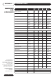
SECTION 2 DIMENSIONS AND CLEARANCES TECHNICAL DATA ANDREWS MODEL NO. Induced Draft Blower: Fasco 7182-6453C; 230V/50Hz. Sealed shaft and seams.
TECHNICAL DATA SECTION 2 Horizontal or Vertical Flue 1168mm Minimum Service clearance with standard Anodes. Adaptor 615mm Minimum Service clearance with Correx Anodes. CSC39 and CSC59 Alternative Flue Systems H I Cold Water Inlet 1 “ B.S.P. Drain or Return 3/4” B.S.P. UNVENTED SYSTEM Ideal Service clearance Dimensions 1125 90.0 275.0 500mm Recommended for panel access and switching. Absolute min 300mm. Horizontal Flue can be rotated 360º 725.0 Min.
SECTION 3 INTRODUCTION INSTALLATION THE LAW REQUIRES THAT INSTALLATION IS CARRIED OUT BY A PROPERLY QUALIFIED PERSON Installations must be carried out in accordance with Gas safety (Installation and Use) Regulations 1998, Building Regulations, The Water Supply (Water Fittings) Regulations 1999 and any requirements of the local Gas Authority, Local Authority, Water and Fire Authorities and the current British Standards and Codes of Practice listed in Section 1.
INSTALLATION SECTION 3 The installation of the gas supply must conform, depending on it's size, to the requirements of British Standards and Codes of Practice listed in Section 1 of this manual. GAS SUPPLY NATURAL GAS A gas meter will be connected to the service pipe by British Gas plc or it's authorised contractor.
SECTION 3 INSTALLATION GAS SUPPLY PROPANE OR BUTANE Contact Calor Gas who will provide the appropriate type and size of LPG supply vessel and ensure it's safe location and installation. The installation of the gas supply must conform to LPGA Code of Practice, 22 LPG Piping Systems: Design and installation plus the requirements of British Standards and Codes of Practice listed in Section of this manual.
INSTALLATION Regulator Set to give 37 mbar (14.
SECTION 3 INSTALLATION ELECTRICAL SUPPLY External wiring to the water heater(s) must be installed in accordance with current I.E.E. Regulations for the wiring of buildings and to any Local Regulations that may apply. The Auto Ignition Heater is designed to operate from a 220/240V, 1Phase supply. The fuse rating is 5 amps.
INSTALLATION SECTION 3 Fig 4.
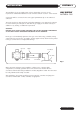
SECTION 3 FLUE SYSTEMS INSTALLATION Your Andrews Water Heater is a Direct Fan Flued Gas Water Heater where all air for combustion is obtained from the outside atmosphere and all flue gases are charged to the outside atmosphere. The flue system is a single coaxial (pipe within pipe) design where the flue products are discharged through the inside flue tube and the combustion air supply surrounds the flue surrounded by the outside pipe.
INSTALLATION SECTION 3 Installation Procedure HORIZONTAL AND VERTICAL DIRECT FLUE LENGTHS Determine location of flue exit. 1. The supplied kit includes a horizontal (through the wall) flue terminal, an elbow, flue connector clamps and 2m (6.5ft) of coaxial flue pipe. The 150mm (6in) diameter flue system is also supplied with a 200mm (8in) to 150mm (6in) reducer for the waterheater flue connection. The coaxial flue pipe includes both the flue exhaust (inside pipe) and combustion air (outside pipe).
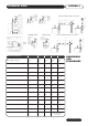
SECTION 3 FLUE SYSTEMS INSTALLATION Optional Components for 150mm (concentric) (6in) Diameter Flue Size Quantity Flue Length Part Description 1 1 mtr Flue Pipe with clamp E202 1 1 mtr Cutable Flue Pipe with clamp E203 1 0.5 mtr Flue Pipe with clamp E204 1 90º Elbow E205 1 45º Elbow E206 Vertical Flue Terminal E239 Flat roof flashing for vertical flue terminal with adjustable cap E207 Roof flashing for pitched roofs 150mm (6in) dia vent size E208 Wall Clamp 150mm (6in) dia.
INSTALLATION SECTION 3 INSTALLING THE FLUE TERMINAL NOTE! The horizontal flue terminal supplied may be used through outside walls up to 600mm (24in) thick. FLUE SYSTEMS 1. Horizontal flue Terminal (Through the Wall) supplied a) Cut an opening of at least 165mm (6.5in) diameter through the outside for the 58.7kWh input models or 216mm (8.5in) for the 88kWh and 105.6kWh input models.
SECTION 3 FLUE SYSTEMS INSTALLATION 2. Vertical Flue Terminal (Through the Roof - Optional) a) Determine the exact location where the roof flue terminal will exit the roof, ensuring the flue system clears all obstructions. For pitched roofs, the flue cap must be the distance above the roof line as specified, (300mm to base of Flue Clamp, minimum). The top of the roof terminal may extend up to 760mm (2.5ft) above the roof line as required.
INSTALLATION SECTION 3 Straight End (Ungasketed) Gasket End Ribs Locked Beneath Gasketed Clamp FLUE SYSTEMS Fig 8. g) The last pipe section may be cut to fit the distance required to reach the water heater flue connections. First, install the supplied condensate trap with crimped end into the gasketed end of the elbow (horizontal flue installations) and clamp the condensate tee and elbow together. Then install the crimped end of the elbow into the flue connection of the water heater.
SECTION 3 AIR SUPPLY AND VENTILATION INSTALLATION The following notes are intended to give guidance: Where the heater is to be installed in a room, NO VENTS ARE REQUIRED. Where the heater is to be installed in a compartment, permanent air vents are required in the compartment at high and low level. These air vents must either communicate with a room or internal space or be direct to outside air.
INSTALLATION IMPORTANT: 1. The effective area requirements specified in the table are related to the maximum heat input of of the heater(s), and are equivalent to those specified in BS6644 and IGE/UP/10 Pt.1 SECTION 3 AIR SUPPLY AND VENTILATION 2. The free area of the grilles should not be less than the size of the recommended ventilation opening. 3. The supply of air to a space housing the heater(s) by mechanical means should be:(a) Mechanical inlet with natural extraction.
SECTION 3 WATER QUALITY AND TREATMENT INSTALLATION Where extreme conditions of water hardness exist, scale can form in any water heating equipment, especially when the heater is working under conditions of constant heavy demand and at high temperatures. Each water heater is fitted with one or more magnesium anode(s) which protects the tank from corrosion caused by electrolytic action. Magnesium anodes are sacrificial in that they corrode as they protect.
INSTALLATION The water heater must be fed from a cold water feed cistern or static water tank. A safety valve must be fitted as specified in BS 6644 Clause 9. SECTION 3 WATER CONNECTIONS VENTED SYSTEMS The safety valve must be fitted either directly to an upper tank tapping or not further than 1 metre along the outlet flow pipe of size not less than the safety valve. There must be no valve separating the heater from the safety valve.
SECTION 3 INSTALLATION WATER CONNECTIONS VENTED SYSTEMS Open Vent Stop Valve Overflow Cold Water Feed Optional Hot Water Service Cold Water Cistern Hot Water Service Secondary Return Check Valve Fig 10.
INSTALLATION SECTION 3 Unvented Systems should be fitted by an Approved Installer When used in an unvented system, the Andrews water Heater will supply hot water at a pressure of 3.5bar (51lbf/in2), provided that this pressure is available at the mains feed. During conditions of no-flow, system pressure may rise to a maximum of 6bar (87lbf/in2) whilst the burner is operating. When testing the system, it is recommended that a maximum test pressure of 8.6bar (125 lbf/in2)is employed.
SECTION 3 WATER CONNECTIONS INSTALLATION If higher flow rates are required for the cold water services, a suitable tee fitting should be fitted to the pipework, upstream of item C1. The pipework fitted to the tundish outlet should be one size larger than the outlet pipe of the safety device and should be terminated at a suitable drain. (See Building Regulations 1992 Approved Document G3).
COMMISSIONING SECTION 4 CAUTION! DO NOT OPERATE THE WATER HEATER UNTIL THE STORAGE VESSEL IS COMPLETELY FILLED WITH WATER, WITH WATER RUNNING FROM ALL HOT TAPS. Open the main gas supply cock after all connections to the gas control are completed and test all connections, using proprietary leak detection fluid. Filling the Heater with Water 1. 2. 3. 4. 5. Close the water heater drain valve. Open the cold water supply valve. Open several hot water taps to allow air to escape from system.
SECTION 4 COMMISSIONING Shutting Off The Burner 1. For long periods only, (7 days or more) move electrical ON/OFF switch to OFF, then turn gas control knob to OFF. Turn off gas service cock. For shorter periods, leave heater under thermostat control. B MV Brown PV/MV Yellow PV Red Gas control Knob Fig 13. A Checking Main Burner Pressure 1. 2. 3. 4. Turn gas control knob to OFF. Release bleed screw (A) and connect pressure gauge tube to port (A). Light burner as described previously.
COMMISSIONING For your safety read before lighting the appliance. WARNING SECTION 4 USER'S SAFETY GUIDE 1. Always follow manufacturer's instructions when lighting the appliance. Failure to do so may result in damage to property, personal injury or loss of life. 2. Before lighting, check all around the appliance area for gas. Be sure to check at low level because some gas (i.e. LPG) is heavier than air and will settle on the floor. 3.
SECTION 5 OPERATION When properly installed and adjusted, the heater will require minimal attention. Should it become necessary to completely drain the heater, follow instructions given in Section 4, Commissioning. Whenever the heater is filled with cold water, condensation will form on the storage vessel surfaces when the burner is lit. This is normal and will disappear when the heater warms up. Operating Sequence 1.
SERVICING Servicing must be carried out by a properly qualified person. SECTION 6 INTRODUCTION Whilst giving these instructions for the care of the Heater, it is recommended that checks are carried out by the installer or local gas authority, at least annually. Ensure good ventilation by keeping the heater free of extraneous materials and clear of dust and lint. Keep pipework, flue and tops of heaters clear of any combustible materials.
SECTION 6 BURNER ASSEMBLY SERVICING Annually, remove the main burner rack assembly to clean orifices and related parts of any dirt or other foreign matter. Inspect the burner ports for obstructions or debris and clean with a wire brush, vacuum, or use a mild detergent to clean as necessary. Inspect the pilot. Carefully clean the electrode and flame sense rod with emery cloth. The spark electrode (rod closest to the pilot hood) gap should be 1/8 in.
SERVICING Check the condition and operation of this component at least once a year to ensure it is free from limescale deposits. Lift the lever at the top of the valve several times until the valve seats properly without leakage and operates freely. SECTION 6 COMBINED TEMPERATURE AND PRESSURE RELIEF VALVE Clean or replace as necessary.
SECTION 7 32 FAULT FINDING FAULT ACTION WATER DOES NOT GET HOT (a) Check gas service cock is open. (b) Check water valves are open. (c) Check thermostat setting. (reset to higher temperature) HEATER SOOTING, YELLOW FLAME (POOR COMBUSTION) (a) Check gas burner. If possible, check heat input with meter and watch. (b) Clean burners and injectors. (c) Flue obstruction. Clean flue ways. (d) Check flue and termination position. (e) Check for correct ventilation.
FAULT FINDING FAULT ACTION RUMBLING NOISE (a) Scale formation in heater, consult water treatment specialist. Heater must be descaled and suitable water treatment provided to avoid re-occurrence. CONTINUOUS IGNITION NO PILOT FLAME (a) Check gas service cock is open. (b) Check gas control knob is ON. (c) Check ECO for failure. PILOT LIGHTS BUT MAIN BURNER DOES NOT (a) Main gas valve not energised. Check for loose contacts. (b) Check for 24V AC at intermittent pilot ignition. Replace control if faulty.
SECTION 8 PARTS LIST AND ILLUSTRATIONS A16 A17 C4 C3 A1 A18 C5 A4 A5 A3 A9 A21 A2 A7 A19 A6 C6 A10 A11 A12 A14 B2 C2 A8 B3 A13 A15 B6 A20 B1 B5 C1 34 B4 B7
PARTS LIST AND ILLUSTRATIONS Model Ref.
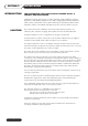
SECTION 9 PARTS LIST AND ILLUSTRATIONS 11 12 10 14 1 9 6 8 2 7 3 5 13 150mm (6in) Flue Kit 10 11 9 13 1 8 7 2 6 3 5 200mm (8in) Flue Kit 36 12
PARTS LIST AND ILLUSTRATIONS Ref. Part No. Description 1 2 3 4 5 6 7 8 9 10 11 12 13 14 E205 E202 E236 E209 E237 E238 E203 E204 E239 E210 E207 E208 E105 E206 90˚ Elbow with Clamp 1 mtr Flue with Clamp Horizontal Flue Terminal Wall Clamp (Not Shown) Large Stepped Adaptor Connection Clamp 200mm (8in) to 150mm (6in) Reducer 1 mtr Cutable Flue with Clamp 0.
SECTION 9 PARTS LIST AND ILLUSTRATIONS C4 C5 C6 C9 C2 C3 C1 C8 C7 Unvented System kit CSC39, 59, 78 & 93 Parts List 38 Ref. Part No.
Wednesbury One, Black Country New Road Wednesbury, West Midlands WS10 7NZ Tel: +44 (0)121 506 7400 Fax: +44 (0)121 506 7401 Email: andrews@andrews-waterheaters.co.uk Website: www.andrewswaterheaters.co.