
Installation guide

TERMINAL
BLOCK
GREEN
LED
yellow
yellow
SUPPLY :-
230Vac / 50Hz
CONSUMPTION :-
(RUN STATE)
PRIMARY 110mAac
25VA max.
brown
brown
blue
blue
green/yellow
white
black
green/yellow
O
STAT ECO
yellow
yellow
yellow
orange
orange
orange
ground
terminal
W (FLAME SENSE)
white
G
G/Y
brown
blue
RED
LED
YELLOW
LED
OVERHEAT
PACTROL P.C. BOARD
FLUE
DAMPER
LINK
TIMER
LINK
F-DET
F-DET
FD 24V
FD 0V
FD2
FD1
GV1
R-PV
BR-MV
Y- PV/MV
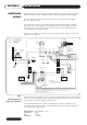
FITTING OPTIONS:-
TO FIT TIMER, MOVE TIMER LINK TO 'ON'
POSITION & CONNECT AS SHOWN.
1.
MVPV
24Vac
24Vac
24Vac
230Vac
INDUCED
DRAFT
BLOWER
GV2
GV
ECO2
GAS
VALVE
GROUND
ECO1
STAT
EARTH
HT
24Vac
MAIN
FLAME
FAILURE
Fan L
NO
COM
NC
TIMER (OPTIONAL)
A.P.S.
L
1
1
L
N
E
EMC
FILTER
N
Fan N
MFF2
MFF1
CH2
CH1
TIM1
TIM2
MAINS
ON
FUSE
315mAT
FUSE
4AT
ON/OFF
24Vac
ON/OFF
SWITCH
GVI/PV
GV2/MV
A.P.S.
E.C.O
F.D.
KEY
FLAME
DETECTION
ELECTRODE
24Vac
IGNITION HT
ELECTRODE
FIRST/PILOT GAS VALVE
SECOND/MAIN GAS VALVE
AIR PRESSURE SWITCH
ENERGY CUT-OFF
FLUE DAMPER
2
1
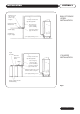
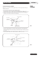
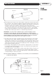
When the Andrews Water Heater is to be connected to a BMS to give a flame failure signal,
the control should be wired as shown.
Te rminals 1 & 2 will give the main flame failure signal.
NORMALLY OPEN
24V AC RELAY
FROM TERMINAL 4 ON RELAY
VOLT FREE
CONTACTS
24V MAX.
INSTALLATIONSECTION 3
External wiring to the water heater(s) must be installed in accordance with current I.E.E.
Regulations for the wiring of buildings and to any Local Regulations that may apply.
The Auto Ignition Heater is designed to operate from a 220/240V, 1Phase supply.
The fuse rating is 5 amps.
The method of connection to the mains electricity supply should facilitate complete
Electrical isolation of the appliance, preferably by use of a fused double pole switch or
fused spur box serving only the heater. The disconnection of the supply shall have a
contact separation of 3mm in all poles.
The point of connection to the mains electricity supply should be readily accessible and
adjacent to the appliance.
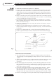
Connect the electrical supply the main control panel terminal block via the cable glands in
the base of the control panel. Mains input cable should be 0.75mm
2
, 3 core, and should
be connected to the mains supply as detailed above.
It is recommended that screen cable is used where the volt-free contacts are to be
connected from an external supply. This will eliminate the risk of possible interference
from nearby high voltage cables.
Mains Voltage: 220/240Volts - IP 20
Frequency: 50Hz
Fuse: 5 Amps
Fan Motor: 1.4 Amps
ELECTRICAL
SUPPLY
10
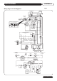
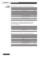
Fig 3.
Wiring diagram for
natural gas appliance.