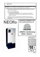
March 2010 NEOflo Condensing Water Heaters Operating, Installation and Servicing Instructions Working towards a cleaner future
Serial No: WARNING: If the information in these instructions are not followed exactly, a fire or explosion may result causing property damage, personal injury or death. - Do not store or use gasoline or other flammable vapours and liquids in the vicinity of this or any other appliance. - WHAT TO DO IF YOU SMELL GAS • Do not try to light any appliance. • Do not touch any electrical switch; do not use any phone in your building. • Immediately call your gas supplier from a neighbour's phone.
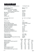
TECHNICAL DATA Gas Category, Type and Supply pressure I 2H G20 @ 20 mbar Permitted Flue Systems Flue Connection Maximum Flue Equivalent Lengths Concentric 80/125 mm Twin (combined length) 80 mm Maximum Flue Temperature Gross Input Net Input Output Gas Rate, NG B23, C13, C33 80 mm 20m FEL 40m FEL 75 °C 26.3 kW 23.7 kW 25.0 kW 2.4 m3/h Combustion NG, CO2, CO NOx Class 9.2 – 9.
IMPORTANT INFORMATION Reproduction of any information in this publication by any method is not permitted unless prior written approval has been obtained from Andrews Water Heaters. Andrews Storage Water Heaters have been designed and manufactured to comply with current International standards of safety. In the interests of the health and safety of personnel and the continued safe, reliable operation of the equipment, safe working practices must be employed at all times. The attention of U.K.
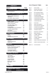
List of Figures & Tables CONTENTS Section TECHNICAL DATA Page Inside cover User Instructions 3 User Control 3 Fig 2.1 General Dimensions 7 Fig 3.1 Open Vent Example 9 Fig 3.2 Re-Circulation Design 9 Fig 3.3 De-Stratification Design 9 Fig 4.1 Unvented Design 11 Fig 5.1 Condensate Soakaway 11 Fig 5.2 Condensate Soil Stack 11 8 Fig 5.3 Condensate Internal Sink 11 8 8 8 10 10 12 12 17 17 18 Fig 5.4 Condensate Gully 11 Fig 6.1 Flue Parts 13 Fig 6.
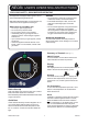
NEOflo USER'S OPERATING INSTRUCTIONS FOR YOUR SAFETY - READ BEFORE OPERATING This appliance is equipped with an ignition device which automatically lights the burner. WARNING * Do not remove or adjust any component part of this water heater; contact the installer. * If this heater developes a fault, such as hot water from a discharge pipe, contact the installer. * Do not use this appliance if any part has been under water.
De-Stratification If your installation has been equipped with a destratification pump wired from the Heater, a Pump symbol will show on the display when it is running. Other symbols If the wrong buttons are pressed it is possible that an engineering mode might be accidentally entered and different symbols will be displayed. In this instance, do not press any buttons for at least 60 seconds and the control will revert back to a normal display.
GENERAL & SAFETY INFORMATION BS 7206: Specification for unvented hot water storage units and packages. The NEOflo range features a stainless steel tank with a stainless steel integrated heat exchanger and a fully automatic electronic control. It also provides mains outputs for Standby, Running and Lockout, for remote use. The following could be relevant dependant upon the installation: I/M2 Purging procedures for non-domestic gas installations.
All Codes of Practice draw attention to the design and operation of water systems with reference to avoidance of factors that favour colonisation by Legionella bacteria. These factors include stagnation, lukewarm conditions (20ºC to 45ºC) and the accumulation of debris, scale and corrosion in the base of tanks and calorifiers. Andrews Water Heaters has commissioned an independent evaluation of their products to investigate their resistance to build-up of Legionella bacteria.
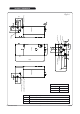
GENERAL DIMENSIONS 380 345 F 164 66 100 45 Electric & BMS entry Fig 2.
The heater is fitted with an inspection point and the tank should be inspected at least annually. (Fig. 2.1 & 9.3) INSTALLATION OF HEATER Location The location selected for installation of the heater must allow the provision of a satisfactory flue, and adequate air supply (for type B23) A purpose built water heater room or compartment is strongly recommended. Water Connections The cold water inlet and hot water outlet connection nipples are identified on top of the appliance.
NEOflo OPEN VENT EXAMPLE Service Valve PT Valve Outlets Minimum 2.0m Service Valve Hot Out Cold In Fig 3.1 Drain NEOflo SECONDARY RETURN DESIGN NEOflo DE-STRATIFICATION DESIGN 3 4 Outlets 2 1 Cold In Hot Out 5 1. Pressure Reducing Valve 2. Non Return Valve 3. Expansion Vessel 4. Pressure Relief Valve Pump 5. Temp & Pressure Relief Valve Pump 6 6. Drain Cock Drain Drain Fig 3.3 Fig 3.
Unvented Water Supply (Fig. 4.1) Condensate Drain Unvented Systems should only be fitted by an Approved Installer Condensation is formed in the heater and this must be continuously discharged into a drain. This can be acomplished by a drop of around 5 mm for every 100 mm of pipework. A trap is supplied which should be connected into a drain via a tundish or air break. (Figs.5.1, 5.2, 5.3, 5.4) The condensate flow must not be allowed to block otherwise the heater will fail to work correctly.
NEOflo UNVENTED SYSTEM DESIGN Expansion Vessel Temperature/Pressure Relief Valve Hot Water Wall Bracket Assembly Hose Assembly Cold Water Inlet of Water Heater Pressure Reducing Valve/Strainer Check Valve Expansion Valve Tundish CONDENSATE DISPOSAL METHODS Balanced Cold Water Take-off (if required) i MIN 110mm FROM A BRANCH PIPE CONDENSATE DISPOSAL METHODS 110MM SOIL / DRAIN ST ACK STACK Fig 4.
Examples: A C33 Concentric flue system that uses one straight length and one 90° bend. 1 x 1m straight length 1.0 1 x 90° bend 1.5 Total (within 20m limit) 2.5 Flue Systems The appliance can be installed using a number of alternative arrangements depending upon the installation requirements It is delivered with its two 80 mm connection points combined into a 80/125 concentric outlet on the left. Flue components are ordered separately as required.
Balanced Flue. FEL NB Do not include the Twin Adapter nor the Terminal 1m length 1.0 45° bend 0.8 90° bend 1.5 Open Flue. FEL NB Do not include the Twin Adapter 1m length 1.0 45° bend 1.0 90° bend 3.5 Horizontal Terminal 5.5 Vertical Terminal 6.
OPEN FLUE EXAMPLE Vertical Terminal Debris Guard 125mm length Horizontal Terminal 80mm Air duct connection Incline 3° back to Heater 80mm Flue duct connection Fig 6.2 HORIZONTAL FLUE EXAMPLE Concentric 90 deg. bend Horizontal Terminal SC 25/200: 375mm SC 25/300: 500mm SC 25/400: 500mm 90 deg. x 80mm bend 80mm Air duct 110mm extension Twin Adapter 80mm Air duct connection Fig 6.
VERTICAL FLUE EXAMPLE Vertical Terminal Concentric 90 deg. bend 90 deg. x 80mm bend 80mm Air duct extension Twin Adapter 80mm Air duct connection Fig 6.4 1000mm Clip pipes every 1000mm 52mm 600 3° 600 FLUE TERMINAL DIMENSIONS L= 0.052 x (G+56) 93 ° 56 G (150 min.) 93 ° NOT>1000mm (tan3°=0.052) 320+L 100 min. 56 Fig 6.
FLUE TERMINAL POSITIONS The flue discharge position for any flue type must conform to the following requirements Fig 6.6 Minimum Distance A B C D E F G H I J K L M N mm Directly below an opening, air brick, opening window etc. Above an opening, air brick, opening window etc. Horizontally to an opening, air brick, opening window etc.
Natural Gas The gas meter, regulator and supply pipework must be sized so as to provide an adequate supply to the Heater in addition to any other appliances connected to the supply. (See Technical Data on the inside cover for Pressure and Flow Rate requirements.) Where the Heater is installed in a plant room or purpose built compartment, a manually operated valve must be fitted in accordance with the Gas Safety (Installation and Use) Regulations. The valve must be easily identified and readily accessible.
Access to the terminal connections (Fig. 7.1) Remove the Lower Front Panel, the Connection Box is facing you on the left hand side. See Fig 7.1. The Connection Box can be completely removed by loosening its fixing screws in its keyhole slots. Electrical Connections IMPORTANT, this appliance must be earthed CAUTION: Isolate the mains electrical supply before starting any work and observe all relevant safety precautions External wiring to the Heater must be installed in accordance with current I.E.E.
WIRING DIAGRAM Fig 7.
COMMISSIONING After installation of the water system, open the main water supply valve, flush the system and fill the heater. Filling With Water 1. Check that the tank drain connection is fitted and closed. 2. If the appliance is connected to a hot water recirculation system, open the isolation valve immediately before the connection point to the tank. 3. Turn on all the hot water draw off taps. 4. Turn on the cold water supply and fill the heater. 5.
Lockouts If the Heater is unable to light or detects a safety condition the control will lockout and the Heater will stop firing. The display will show RESET and a number referring to the type of error. See the table above. To clear a Lockout press the RESET button and provided the condition has been corrected the Heater will try to light. There is a second reset button and indicator on the Burner Control behind the lower front panel.
Diagnostics The Display can provide additional information whilst Running, In Standby and In Error, when the buttons are pressed. The table below details the sub-sections available. Pressing Service A, Service B and Reset together will, test all the segments of the LCD display.
SERVICING Spark & Sense Electrode Health and Safety Statement : This Heater contains no asbestos. Turn off the Heater. Pull off the HT and Earth leads. Remove the cover over the Ignition Control connections and pull it off the Gas Valve. Undo the two screws retaining the electrode assembly and carefully withdraw. The spark gap should be 3.0 mm ± 0.5. Assembly is the reverse, ensuring the gasket is correctly placed.
Unclip the Sensor Retainer and withdraw the Sensor. Trace the sensor cable back to its in-line two way connector, de-latch and disconnect. Replacement is the reverse. Throttle Adjustment Flue Thermostat (Fig. 9.4) This is located on the Sump Flue Connection. Remove the Lower Front Panel. Pull off the electrical connector. Undo from the Flue Connection. Replacement is the reverse. Ignition Control (Fig.9.4) Fig 9.1 Remove the Lower Front Panel.
Fan (See Fig. 9.4) Venturi (Fig. 9.4) Remove the Lower Front Panel. Remove the electrical connector on the Fan. Remove the two screws holding the Venturi to the Fan. Undo the four screws holding the Fan to the Fan Mounting and remove. Ensure the Baffle Plate and Fan Gasket is retained on the Fan Mounting. (Fig. 9.4) Transfer the Venturi gasket to the new fan. Replacement is the reverse. Remove the Lower Front Panel. Pull off the Air Tube (Fig. 9.
HEATER COMPONENTS EXTERNAL Tank Inspection Hatch Temperature & Pressure Relief Valve High Limit Sensor Removable Cover (To access Control Sensor) Display Panel Control Sensor Door Fig 9.
HEATER COMPONENTS INTERNAL Combustion Test Point Flue Thermostat Spark & Sense Electrode Ignition Lead Fan Mounting Spacer Fan Gasket Wiring Connection Box Ignition Control Flue Elbow Release Gas Cock Condensate Pipe 41mm Gas Valve Air Duct Cylinder Drain Pipe 22mm Fig 9.
INSTALLATION & SERVICE HISTORY Tick appropriate: SC25/200 Model SC25/300 SC25/400 Commissioning Installer Registration No Working pressure CO ppm Instructed User in operation? Date: mbar CO2 % Yes/No Service Record Date Cleaned ? Pressure CO CO2 Date Cleaned ? Pressure CO CO2 Date Cleaned ? Pressure CO CO2 NEOflo 02/02/09
Baxi Commercial Division Wood Lane, Erdington, Birmingham B24 9QP Email: andrews@baxigroup.com www.andrewswaterheaters.co.