
Technical data


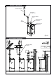

Unvented Water Supply (Fig. 4.1)
Unvented Systems should only be fitted by an
Approved Installer
When using the Heater on an unvented hot water
storage system, the Unvented System Kit, part
number B314, available from Andrews Water Heaters
must be fitted. See Parts List Page 25.
When used in an unvented system, the Heater will
supply hot water at 3½ bar or the pressure available
at the mains feed if this is lower. During conditions of
no-flow, system pressure may rise to a maximum of
6 bar, whilst the burner is operating. When testing
the system, it is recommended that a maximum test
pressure
of 7bar is employed.
A 25 litre expansion vessel is suitable for the stored
volume of all models of the Heater and an average
pipework system.
FOR SYSTEMS WITH LARGER PIPE VOLUMES
OR ADDITIONAL STORAGE, EXPANSION VES-
SELS WITH GREATER CAPACITY ARE AVAILABLE.
Assemble the components of the unvented system
kit as shown in Fig. 4.1.
IMPORTANT: When assembling the Pressure
Reducing Valve and Double Non-return Valve, ensure
that the flow arrows marked on the
components are
pointing in the direction of flow i.e. towards the
Heater.
The relief valves fitted to this appliance must not be
used for any other purpose.
No fitting should be installed between the expansion
valve and the cylinder.
The cold water for services may be drawn from the
22mm compression port on Pressure Reducing
Valve. The water pressure at this point will be similar
to that available at the hot water outlet of the water
heater. If this port is not used, it should be sealed
with the blanking plug supplied.
If higher flow rates are required for the cold water
services, a suitable tee fitting should be fitted to the
pipework, upstream of the Pressure Reducing Valve.
The pipework fitted to the tundish outlet should be at
least 28mm diameter and made of metal it should be
terminated at a suitable drain (see Building Regula-
tions Approved Document G3).
All fittings and materials supplying water to the
storage vessel must be suitable for use with drinking
water and listed in the current Water Research
Centre “Materials and Fittings Directory”.
Installation of unvented hot storage water systems
must comply with Part G of Schedule 1 of the Build-
ing Regulations.
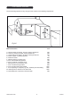
Condensate Drain
Condensation is formed in the heater and this must
be continuously discharged into a drain. This can
be acomplished by a drop of around 5 mm for every
100 mm of pipework. A trap is supplied which
should be connected into a drain via a tundish or air
break.
(Figs.5.1, 5.2, 5.3, 5.4)
The condensate flow must not be allowed to block
otherwise the heater will fail to work correctly.
NOTE: An air break is required downstream of the
trap to protect the Heater from blockages and
subsequent damage. The appliance can produce up
to 2 litres of condensate per hour.
Never discharge the condensate into a sink, bath,
bidet or toilet etc.
The condensate trap must be connected in a
minimum diameter of 19 mm plastic pipe inside a
building.
External pipework and that passing
through a wall to the outside should be run in a min
of 32mm diameter. All external pipework should be
insulated to protect against frost.
The length of external drain pipe should be kept as
short as possible and not more than 3m.
NEOflo Water Heater 10 02/02/09