
Technical data


NEOflo Water Heater 25 12/03/10
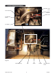
Fan (See Fig. 9.4)
Remove the Lower Front Panel.
Remove the electrical connector on the Fan.
Remove the two screws holding the Venturi to
the Fan.
Undo the four screws holding the Fan to the
Fan Mounting and remove.
Ensure the Baffle Plate and Fan Gasket is
retained on the Fan Mounting. (Fig. 9.4)
Transfer the Venturi gasket to the new fan.
Replacement is the reverse.
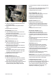
G061 O ring, gascock
G062 Gas Valve
G063 Electrode gasket
G064 Electrode
G065 Burner Insulation
G066 Burner
G067 Ignition Lead
G068 Pressure & Temperature Relief Valve
G069 Venturi
SPARE PARTS
B314 Unvented Kit
G070 Fan Gasket
G071 Fan
G072 User LCD Control
G073 Burner Control
G074 Flue Thermostat
G075 High Limit Sensor
G076 Pocket, Thermostat
G077 Control Sensor
Venturi (Fig. 9.4)
Remove the Lower Front Panel.
Pull off the Air Tube (Fig. 9.4)
Undo the three screws holding the Venturi to
the Gas Valve.
Undo the two screws holding the Venturi to
the Fan and remove.
Ensure the gasket is transferred to the new
venturi or positioned on the Fan before posi-
tioning the replacement.
Ensure the rubber gasket between the Gas
Valve and Venturi is correctly positioned.
Replacement is the reverse.
Light the Heater and check for gas leaks.
After five minutes check the rate and combus-
tion is correct to the Datatable. (inside Front
cover). Adjust using the Throttle Screw on the
Gas Valve clockwise to decrease CO
2
, anti-
clockwise to increase CO
2
. (Fig. 9.1)
Fig 9.2
Earth connection
On/Off Switch
connections
LCD PCB
LCD DISPLAY