This manual must be kept with the appliance January 2011 Part No E104 RSC 150 / RSC 190 Permanent Pilot, Auto Ignition Installation Guide, Operation & Service Manual Working towards a cleaner future
© Copyright Andrews Water Heaters 2007 Reproduction of any information in this publication by any method is not permitted unless prior written approval has been obtained from Andrews Water Heaters. Andrews Storage Water Heaters have been designed and manufactured to comply with current International standards of safety. In the interests of the health and safety of personnel and the continued safe, reliable operation of the equipment, safe working practices must be employed at all times. The attention of U.
CONTENTS SECTION 1 PAGE GENERAL AND SAFETY INFORMATION General Information British Standards and Codes of Practice Health and Safety Regulations 1993 Effectiveness in Combating Legionellae 2 2 3 3 SECTION 2 TECHNICAL DATA 4 SECTION 3 INSTALLATION Location Flue Systems Air Supply and Ventilation Electrical Supply (Auto Ignition) Water Connections Water Quality & Treatment Hydrojet Systems Vented Systems Unvented Systems Gas Connections SECTION 4 COMMISSIONING To To To To To To SECTION 5 Light th
SECTION 1 GENERAL INFORMATION GENERAL AND SAFETY INFORMATION The Andrews Water Heater has been designed for use with NATURAL GAS only and is manufactured to give an efficient, reliable and long service life. To ensure the continued, trouble-free operation of your heater at maximum efficiency, it is essential that correct installation, commissioning, operation and service procedures are carried out strictly in accordance with the instructions given in this manual.
GENERAL AND SAFETY INFORMATION It is the duty of manufacturers and suppliers of products for use at work to ensure, so far as is practicable, that such products are safe and without risk to health when properly used and to make available to users, adequate information about their safe and proper operation. Andrews Water Heaters should only be used in the manner and purpose for which they were intended and in accordance with the instructions in this manual.
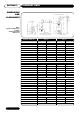
SECTION 2 TECHNICAL DATA DIMENSIONS AND CLEARANCES Recommended Service Clearance E H K 200mm GRS Cold F Hot M 170mm 65⁄8” Fig 1. Appliance Dimensions Including Standard Flue Run Dimensions Recommended Service Clearance Recommended Service Clearance 180˚ I D G L A B C J Concentric Flue External Flue diameter 125mm (5”) Internal Flue diameter 80mm (3”) Minimum Service Clearance ANDREWS MODEL NO.
INSTALLATION SECTION 3 THE LAW REQUIRES THAT INSTALLATION IS CARRIED OUT BY A PROPERLY QUALIFIED PERSON Install in accordance with current British Standard Code of Practice 342 part 2 and British Standards 5440, 5546, 6644, 6700, 6798 and 6891. The location chosen for the heater must permit the provision of a satisfactory flue and an adequate air supply.
SECTION 3 INSTALLATION RSC150 & RSC190 Flue Fitting Instructions 1. Fit heater adaptor D1 to heater ensuring correct location on primary flue spigot from heater. (Use 4 self tapping screws provided). 2. Fit flue restrictor ring D7 into heater adaptor D1 The correct size of restrictor for each heater model and installation is shown on page 5. 3. Fit flue section D2 into heater adaptor D1. 4. Fit elbow D4 into flue section D2 for horizontal flue runs. 5.
INSTALLATION SECTION 3 Note: - Both air vents must communicate with the same room or internal space or must both be on the same wall to outside air. Air vents should have negligible resistance and must not be sited in any position where they are likely to be easily blocked or flooded or in any position adjacent to an extraction system which is carrying flammable vapour. Consideration must be given to the position of the high level ventilation opening.
SECTION 3 INSTALLATION ELECTRICAL SUPPLY AUTO IGNITION UNITS External wiring to the water heater(s) must be installed in accordance with current I.E.E. Regulations for the wiring of buildings and to any Local Regulations that may apply. The Auto Ignition Heater is designed to operate from a 220/240V, 1Phase supply. The fuse rating is 5 amps.
INSTALLATION SECTION 3 To ensure long life and efficient, reliable performance from Andrews water heaters it is essential that the water heater is installed and serviced in accordance with the manufacturers instructions. Each water heater is fitted with one or more magnesium anode(s) which protect the tank from corrosion caused by electrolytic action within water systems. The magnesium anodes are sacrificial and as such they erode as they offer protection.
SECTION 3 WATER CONNECTIONS VENTED SYSTEMS INSTALLATION The water heater must be supplied from a cold water feed cistern and the hot water supply pipe must be fitted with an open vent pipe in accordance with BS 5546. Local regulations and bye-laws must be observed when installing the system but typical water service layouts are shown in Fig. 3.
INSTALLATION When used in an unvented system, the Andrews storage water heater will supply hot water at a pressure of 3.5 bar (50.8 psi) providing this pressure is available at the mains feed. During conditions of no flow, whilst the burner is operating, the pressure of the system will rise to a maximum of 6 bar (87.0 psi). When testing the system it is recommended that a maximum test pressure of 8.62 bar (125 psi) be employed.
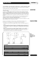
SECTION 3 INSTALLATION F3 F8 F4 F1 (a) F7 F2 F5 F6 Fig. 4 Unvented Systems Kit Ref Part No.
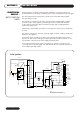
INSTALLATION SECTION 3 WATER CONNECTIONS F3 Expansion Vessel Balanced Cold Water Take-off (if required) F4 Temperature/ Pressure Relief Valve F8 Wall Bracket Assembly F7 Hose Assembly Cold Water Inlet to Water Heater F2 Check Valve/ Expansion Valve F5 Reducing Bush F1 Pressure Reducing Valve/ Strainer F6 Tundish Cold Water Feed NB. Tees, elbows, stop valve and pipework not supplied. Fig.
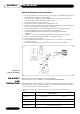
SECTION 3 INSTALLATION WATER CONNECTIONS F3 F1 Hot water service F5 F4 Cold Water Take Off F2 F6 Secondary Return Cold Water Inlet Check Valve Fig. 6 Typical Installation, Unvented System GAS CONNECTIONS To drain THE APPLIANCE MUST ONLY BE USED WITH NATURAL GAS. The installation of the gas supply should conform to the requirements of IM/16 published by British Gas p.l.c. or BS 6891. Jointing compound used must conform to BS 6956 Pt 5.
COMMISSIONING SECTION 4 CAUTION: DO NOT OPERATE THE WATER HEATER UNTIL THE STORAGE VESSEL IS COMPLETELY FILLED WITH WATER, WITH WATER RUNNING FROM ALL HOT TAPS. Open the main gas supply cock after all connections to the gas control thermostat are complete, and test all connections with soap solution. GAS CONNECTIONS 1. Remove outer cover wait 3 minutes for any unburnt gas to vent. 2. Turn the gas control knob to pilot. (see below) 3. Fully depress the gas control knob and the piezo ingnitor.
SECTION 4 COMMISSIONING LIGHTING THE BURNER AUTO IGNITION Thermostat Control Knob On/Off Switch Gas Control valve 1. 2. 3. 4. 5. Ensure gas supply is on. Set thermostat control knob to the required water temperature. (See below). Ensure time switch if fitted is in the ON position. Move electrical ON/OFF switch to ON and the burner will light. Check pilot and main gas connections at gas control valve using leak detection fluid whilst burner is alight. Turn OFF, seal any leakages then re-test.
OPERATION SECTION 5 When properly installed and adjusted the Heater will require the minimum of attention. Should it become necessary to completely drain the heater, close the cold water inlet valve, open a hot water tap to allow air to enter the system. Fit a suitable hose to the drain cock and open. Whenever the Heater is filled with cold water, condensation will form on the cold storage vessel surfaces when the burner is lit. Condensation is normal and does not indicate a leak.
SECTION 6 SERVICING Whilst giving the following instructions for the care of the Andrews Water Heater, we would recommend that an arrangement is made with your local gas region or installer to carry out periodic checks of the appliance to ensure trouble free operation and continued satisfaction. BURNER ASSEMBLY The burner assembly should be cleaned and checked annually as follows:1. Depress slightly the gas control knob and turn to "OFF". Remove the outer burner cover and the inner door.
SERVICING The burner should be checked annually. The flueway and baffle should be checked if sooting occurs and if necessary cleaned as follows:- SECTION 6 FLUEWAY 1. Depress slightly the gas control knob and turn to "OFF". Remove outer burner cover and inner cover. Remove the fixing screws to remove the inner cover. 2. Disconnect burner gas tube, pilot tube and thermocouple at gas control. 3. Remove burner assembly complete with pipes and thermocouple lead. 4.
SECTION 7 FAULT FINDING ACTION FAULT 1. WATER DOES NOT (a) Check (b) Check GET HOT (c) Check (d) Check (e) Check (f) Check gas cock is open. water valves are open. that pilot is alight. thermostat setting. (Reset to higher temperature). gas pressures at burner and at gas inlet to appliance. cold inlet dip tube to see if it is broken or missing (see Fig. 10). 2. PILOT FLAME IS OUT (a) Try to light burner as detailed in lighting instructions.
FAULT FINDING FAULT ACTION NO IGNITION AT PILOT (a) Check gas service cock is open. (b) Electrical ON/OFF switch is not ON. (c) Power to unit interrupted. (d) Thermostat set too low. (e) Check ECO for failure. Reset. (f) Check for 24V AC at intermittent pilot ignition control terminal No. 1. Replace control if faulty. (g) Faulty Solenoid Coil. Replace if faulty. PILOT LIGHTS BUT MAIN BURNER DOES NOT (a) Check for 24V AC at intermittent pilot ignition control terminal No. 3. Replace control if faulty.
SECTION 8 PARTS LIST AND ILLUSTRATION RSC150/RSC190 Model RSC150 RSC190 Ref Part No. Part No.
PARTS LIST AND ILLUSTRATION RSC150/RSC190 Model RSC 150 RSC 190 Ref Part No. Part No. D1 D2 D3 D4 D5 D6 D7 D7 D7 D7 D7 D8 D9 D10 E072 E069 E073 E071 E067 E075 E074 E076 E072 E069 E073 E071 E067 E075 Qty Heater Adaptor 0.
SECTION 8 PARTS LIST AND ILLUSTRATIONS 24 Volt Auto System Kit B217 24 Volt Auto System Kit Standard Range 24 Part No.
NOTES 25
NOTES 26
Baxi Commercial Division Wood Lane, Erdington, Birmingham B24 9QP Email: andrews@baxigroup.com www.andrewswaterheaters.co.