This manual must be kept with the appliance October 2010 Part No E791 FASTflo (internal) Installation Guide, Operation and Maintenance Manual Continuous Flow Wall Hung Balanced Flue Water Heaters for Natural Gas and LPG WH42, WH56, LWH42, LWH56 Working towards a cleaner future
SECTION XX • INTRODUCTION Reproduction of any information in this publication by any method is not permitted unless prior written approval has been obtained from Andrews Water Heaters. Andrews Storage Water Heaters have been designed and manufactured to comply with current international standards of safety. In the interests of the health and safety of personnel and the continued safe, reliable operation of the equipment, safe working practices must be employed at all times.
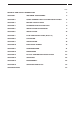
CONTENTS PAGE GENERAL AND SAFETY INFORMATION 4 SECTION 1 INCLUDED ACCESSORIES 5 SECTION 2 QUICK CONNECT MULTI SYSTEM INSTALLATION 6 SECTION 3 BEFORE INSTALLATION 7 SECTION 4 CHOOSING INSTALLATION SITE 8 SECTION 5 INSTALLATION CLEARANCES 9 SECTION 6 INSTALLATION 10 SECTION 7 FLUE PIPE INSTALLATION (External) 11 SECTION 8 GAS PIPING 17 SECTION 9 WATER PIPING 18 SECTION 10 ELECTRICAL WIRING 19 SECTION 11 COMMISSIONING 21 SECTION 12 DIMENSIONS 23 SECTION 13 Remote CONTROL
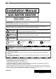
GENERAL SAFETY INFORMATION Installation Manual GAS WATER HEATER WH42, LWH42 WH56, LWH56 (Internal) (Internal) WARNING: If the information in this manual is not followed exactly, a fire or explosion may result causing property damage, personal injury or death. Potential dangers from accidents during installation and use are divided into the following three categories. Closely observe these warnings, they are critical to your safety.
INCLUDED ACCESSORIES 1. Included Accessories Part Shape 5 The following accessories are included with the unit. Check for any missing items before starting installation.
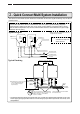
QUICK CONNECT MULTI SYSTEM INSTALLATION 2. Quick Connect Multi System Installation • The Quick Connect Multi System allows the installation of two units together utilizing only the Quick Connect Cord. The Quick Connect Cord is 2m. long. Install the two units 470mm-950mm apart at the center to ensure the cord will be able to reach between the units. (See Typical Plumbing diagram).
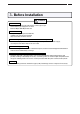
BEFORE INSTALLATION 3. Before Installation Caution Check the Gas • Check that the rating plate indicates the correct type of gas. Check that the gas supply line is sized for 62.3 kW(or 49.0 kW) for this unit. Check the Power • The power supply required is 230V AC, at 50Hz. Using the incorrect voltage may result in fire or electric shock.
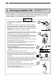
CHOOSING AN INSTALLATION SITE 4. Choosing Installation Site The appliance must be installed in a suitably ventilated room, in accordance with the regulatins in force. * Locate the appliance in an area where leakage from the unit or connections will not result in damage to the area adjacent to the appliance or to the lower floors of the structure. When such locations cannot be avoided, it is recommended that a suitable drain pan, adequately drained, be installed under the appliance.
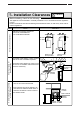
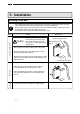
INSTALLATION CLEARANCES 5. Installation Clearances 9 Caution Before installing, check for the following: The appliance must be installed in a suitably ventilated room, in accordance with the regulations in force. Install in accordance with relevant building and mechanical codes, as well as any local, state or national regulations. Distance from combustibles Item Check Illustration • Maintain the following clearances from both combustible and non-combustible materials.
INSTALLATION 6. Installation Securing to the wall • The weight of the device will be applied to the wall. If the strength of the wall is not sufficient, reinforcement must be done to prevent the transfer of vibration. • Do not drop or apply unnecessary force to the device when installing. Internal parts may be damaged and may become highly dangerous. • Install the unit on a vertical wall and ensure that it is level.
FLUE PIPE INSTALLATION 11 7. Flue Pipe Installation (Internal Installation Only) Flue Terminal Installation • Follow the installation instructions included with the flue terminal and which are reproduced at the end of this manual. This appliance must be the flue through the wall, not vertically to the roof.
FLUE PIPE INSTALLATION Detailed recommendations for the flue installations are given in BS 5440:1:2000. The following notes are for general guidance only. Note: An adapter is always required on top of the heater. For the vertical flue set up, offset adapter will be supplied for the air intake. a) The flue system must be constructed using only ANDREWS WATER HEATERS approved components. b) It is important that the position of the terminal allows free passage of air across it at all times.
FLUE PIPE INSTALLATION 13 Installing Horizontal Extended Terminal Important: The flue terminal must be installed horizontally. 1. Mark the centre of the 152mm diameter hole and core drill. Note: If the wall is clad with a combustible material an additional 25mm wide area must be removed around liner. 2. Measure the wall thickness and cut the liner to this length. Note: Cut opposite end to rim and allow some material to be used as tabs on the inside of the wall to ensure a secure fixing.
FLUE PIPE INSTALLATION M&G HORIZONTAL FLUE TERMINAL • Use only the following models of the flue terminals with this unit. • The M&G Horizontal Flue Terminal can be cut to suit the wall thickness. Wall thickness 50 mm to 500 mm Flue Precautions • Use 100mm diameter flue pipe.
FLUE PIPE INSTALLATION 15 M&G VERTICAL FLUE TERMINAL • Use only the following models of the flue terminals with this unit. • The M&G Vertical Flue Terminal can be cut to suit the roof. Roof thickness 50 mm to 500 mm Flue Precautions • Use 100mm diameter flue pipe.
FLUE PIPE INSTALLATION Connecter for switching airflow rate depending on exhaust conditions Under the exhaust conditions indicated by the shaded portion of the table below, the connector for switching the airflow rate shown in the illustration below is pulled out. (Changes the speed of fan rotation.
GAS PIPING 8. Gas Piping 17 Follow the instructions from the gas supplier. The appliance and its individual shutoff valve must be disconnected from the gas supply piping system during any pressure testing of that system at test pressures in excess of 35 mbar. The Appliance must be isolated from the gas supply piping system by closing its individual manual shutoff valve during any pressure testing of the gas supply piping system at test pressures equal to or less than 35 mbar.
WATER PIPING 9. Water Piping Ask a qualified plumber to perform the installation of the plumbing. Observe all applicable codes. This appliance is suitable for potable water. Do not use this appliance if any part has been underwater. Immediately call a qualified service technician to inspect the appliance and replace any part of the control system and gas control which has been under water.
ELECTRICAL WIRING 10. Electrical Wiring 19 Consult a qualified electrician for the electrical work. Do not connect electrical power to the unit until all electrical wiring has been completed. i) "A means of disconnection from the supply mains having a contact separation in all poles must be provided to allow for full disconnection". ii) Under voltage Cat III conditions should be incorporated in the fixed wiring in accordance with the wiring regulations.
ELECTRICAL WIRING Remote Controller • Applicable Model WH42, LWH42, WH56, LWH56 Remote controller • Main RC-7508M The remote controller must be installed in accordance with the installation manual enclosed in the package. Connecting Remote Controller Cord to Unit • • • • Keep the remote controller cord away from the freeze prevention heaters in the unit. Tie the redundant cord outside the water heater. Do not put the extra length inside the equipment.
COMMISSIONING 11.Commissioning 21 The installer should test operate the unit, explain to the customer how to use the unit, and give the owner this manual before leaving the installation NOTE: The appliance has been factory set and no adjustment is necessary. • Preparation ... (1) Ensure all lines are purged / flushed of debris prior to connection to appliance. (2) Open the shut off valve on the water supply, check that water passes through the valve and close the valve.
COMMISSIONING Lighting Instructions This water heater does not have a pilot. It is equipped with an ignition device that automatically lights the burner. 1. Read the safety information in the installation manual or on the front of the water heater. 2. Turn off all electrical power to the unit. 3. Do not attempt to light the burner by hand. 4. Turn the gas control manual valve (external to the unit) clockwise to the off position. 5. Wait five minutes to clear out any gas.
DIMENSIONS 23 12. Dimensions WH42, LWH42, WH56, LWH56 (unit: mm) (VIEW FROM TOP) 361 244 GAS INLET (3/4) 450 140 87 71 173 89 61 COLD WATER INLET (3/4") HOT WATER OUTLET (3/4) WIRING THROUGHWAYS 464 170 140 100 10 450 240 150 94 AIR INLET 39.
DIMENSIONS Wiring Diagram ( WH42, LWH42, WH56, LWH56) BR BR W 1 2 3 (UN-USED) (VACANT CONNECTOR) AIRFLOW CHANGE -OVER CONNECTOR R W 1 2 3 4 5 6 7 (VACANT CONNECTOR) BL 1 2 3 4 5 6 BL BL 15 14 13 12 11 10 9 8 7 6 5 4 3 2 1 1 2 3 4 5 6 7 8 9 MAIN CIRCUIT BOARD INLET WATER THERMISTOR W 3 W 2 W 1 W HEAT EXCHANGER THERMISTOR W W 4 W 3 2 W 1 W W W 2 W W 1 W OPERATING LED 2 1 BK W SM (VCC) LS (VCC) (Fully open) (GND) 2 1 4 3 6 5 8 7 10 9 12 11 14 13 16 15
REMOTE CONTROLLER INSTALLATION 13.Remote Controller Installation Manual Model Number: 25 For Installers: Read this installation guide carefully before carrying out installation. RC-7508M Note Do not connect power to the water heater before the remote controller has been properly installed.
SERVICING • DISASSEMBLY 14. Servicing Important Notes To ensure the continued efficient and safe operation of the boiler it is recommended that it is checked and serviced at regular intervals. The frequency of servicing will depend upon the particular installation and usage, but in general once a year should be enough. It is the Law that any servicing is carried out by a competent person.
DISASSEMBLY (2) Remove the 2 locking screws of the transformer, then pull out. 2. Removing the electric board (1) Remove the locking screws at the top and bottom and ground screw, then pull board out. 3. Removing the manifold • Remove the electric board and fixing plate of the ground-fault circuit interrupter in advance. (1) Remove the locking screw of the gas electromagnetic valve and the manifold pipe.
DISASSEMBLY (2) Remove the fasten terminal of the gas electromagnetic valve, then remove the 4 manifold locking screws. (3) Pull up and remove the manifold. 4. Removing the hot-water supply fan • Remove the electric board, manifold and intake gas pipe in advance. (1) Remove the 3 fan locking screws, then pull out.
DISASSEMBLY (2) Pull out the fan motor. 5. Removing the gas electromagnetic valve block • Remove the electric board and manifold in advance. (1) Remove the gas electromagnetic valve locking screw. (2) Pull up the gas electromagnetic valve to the upper section and remove it.
DISASSEMBLY 6. Removing the mixing tube block • Remove the electric board and connectors in advance. (1) Remove the locking screw of the intake water pipe and the locking quick fastener of water flow sensor set 3 of the heat exchanger, then pull out the intake water pipe. For Quick-discharge type Remove the intake water pipe locking screw and 2 locking fasteners of the non-return valve, then remove the intake water pipe and pull out the pump discharge pipe.
DISASSEMBLY (4) Pull up the mixing tube block to the upper section and remove it. 7. Removing the heat exchanger • Remove the electric board, manifold, mixing tube block and connectors in advance. (1) Remove the 3 locking screws at the bottom of the burner case. (2) Remove the 2 case top plate locking screws. (3) Remove the 3 locking screws at the flue collar and adapter, pull out the heat exchanger.
SERVICING PARTS LIST 16.
SERVICING PARTS LIST External outfitting WH42, LWH42, WH56, LWH56 Part Nos. Part Names Order Nos.
SERVICING PARTS LIST Combustion unit and gas route WH42, LWH42, WH56, LWH56 100 109 102 101 105 110 117 103 126 116 131 070 104 072 117 070 132 070 118 129 173 128 073 171 172 170 111 112 114 070 119 125 141 115 070 070 173 133 175 175 For LWH42 For LWH56 122 3P 3P 121 121 120 123 172 171 124 127 172 075
SERVICING PARTS LIST Combustion unit and gas route WH42, LWH42, WH56, LWH56 Part Nos. Part Names Order Nos.
SERVICING PARTS LIST Hot-water feed route WH42, LWH42, WH56, LWH56 412 425 456 424 413 428 402 A 434 401 508 507 427 456 421 D 433 412 434 423 468 406 B 413 484 510 402 483 407 400 470 417 402 402 C 173 471 408 412 472 406 435 452 414 409 471 172 413 456 410 511 418 412 509 434 413 441 411 075 511 422 A 456 413 508 412 507 B 420 073 463 428 468 D 453 435 458 434 444 442 454 434 172 456 437 434 172 445 434 439 456 C 443 418 509 44
SERVICING PARTS LIST Hot-water feed route WH42, LWH42, WH56, LWH56 (Thermal fuse rounding procedure) (Left side view) (Front side view) (Right side view) (Rear side view) Freeze preventive heater 1.
SERVICING PARTS LIST Hot-water feed route WH42, LWH42, WH56, LWH56 Part Nos. Part Names Order Nos.
SERVICING PARTS LIST Electronic control unit WH42, LWH42, WH56, LWH56 705 701 F G 700 H 073 703 732 070 714 710 715 070 717 711 722 H 070 712 070 070 730 731 721 733 073 721 713 G F 39
SERVICING PARTS LIST Electronic control unit WH42, LWH42, WH56, LWH56 Part Nos. Part Names 700 701 Relay case ELE-A SET-AS Harness AD ELE 703 Lamp cable conduit 705 710 Relay case cover DEK Mounting plate for terminal block 711 712 CRP Order Nos.
SERVICING PARTS LIST Remote controller and Attached set WH42, LWH42, WH56, LWH56 Optional Accessories Remote controller (RC-7508M) 751 787 788 786 752 Attached set 803 804 805 Special part Special part no.
SERVICING PARTS LIST Remote controller and Attached set WH42, LWH42, WH56, LWH56 Part Nos. Part Names Order Nos. Q'ty/unit 1 1 751 752 RC-7508M Body AD(SE) QPA M Dressed frame body AD(SE) QPA QPAJ013 QPAA013 786 787 Oar plug 6X25 Cross recessed flat-head screw M4X35 6339000 SHB6879 788 Cross recessed flat-head wood screw (All screw)4.1X20 SHC6365 800 803 GQ3211WZFF2AD packing set V Cross recessed round-head type 1 tapping screw 5X35 SKA7265 SAC6208 1 804 Crescent clamp 18.
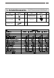
SPECIFICATIONS 43 Specifications Specification Item Model Name Type WH42 Installation Air Supply/Exhaust Ignition Minimum Pressure for Maximum flow Minimum Flow Rate Dimensions Weight Water Holding Capacity Connection Sizes Water Inlet Power Supply Materials Hot Water Outlet Gas Inlet Supply Consumption Casing Flue Collar Heat Exchanger LWH42 Internal, Wall Hanging Power Flue Direct Ignition 2.0 bar 2.5 L/min. 61.5 cm(Height) x 46.4 cm(Width) x 24 cm(Depth) 29 kg 1.
SPECIFICATIONS Specifications Specification Item Model Name Type WH56 Installation Air Supply/Exhaust Ignition Minimum Pressure for Maximum flow Minimum Flow Rate Dimensions Weight Water Holding Capacity Connection Sizes Water Inlet Power Supply Materials Hot Water Outlet Gas Inlet Supply Consumption Casing Flue Collar Heat Exchanger LWH56 Internal, Wall Hanging Power Flue Direct Ignition 2.0 bar 2.5 L/min. 61.5 cm(Height) x 46.4 cm(Width) x 24 cm(Depth) 29 kg 1.
Baxi Commercial Division Wood Lane, Erdington, Birmingham B24 9QP Email: andrews@baxigroup.com www.andrewswaterheaters.co.