
Assembly Instructions

E4T Assembly Instructions
support@usdigital.com
▪
www.usdigital.com
Local: 360.260.2468
▪
Sales: 800.736.0194
Support: 360.397.9999
▪
Fax: 360.260.2469
1400 NE 136
th
Ave.
▪
Vancouver, Washington
▪
98684
▪
USA
USD-4203
v6.0
Page 1
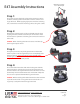
Step 1:
Place the base over the shaft and onto the mounting surface.
Slide the centering tool onto the shaft so that it contacts and
aligns the base. While applying light pressure to the centering
tool, secure the base to the mounting surface using two screws.
Step 2:
Remove the centering tool and place the PCB onto the base,
aligning the hole and slot to the two pins on the base. Note
that the base is symmetrical allowing the connector to exit out
either side.
Caution: When handling the PCB it is best to avoid directly
touching the optical sensor.
Step 3:
Using the spacer tool, very firmly press down on the PCB in
order to push it over the alignment pins and completely onto
the base surface. Check to make sure that the PCB is fully
seated against the base. If it is not, use the spacer tool to press
it again, recheck that it is fully seated.
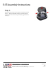
Step 4:
Place the hubdisk onto the shaft with the longer end of hub
toward the base. Position the spacer tool onto the hub such
that the notches are aligned with the latches of the base. Press
down firmly until the tool bottoms out on the PCB. Verify that
this action has pressed the PCB flush against the base.
Caution: While installing the hubdisk ensure that the hub bore
is parallel to the shaft. Forcing the hub onto the shaft at an
angle may cause permanent damage to the hub.
Mounting Screws:
2-3 in-lbs torque