
Manual


18
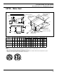
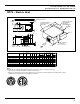
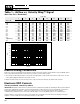
QPTW – Water Heat
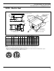
DISCHARGE VIEW
INLET VIEW
PRIMARY
AIR FLOW
DISCHARGE
OUTLET
X x Y
H/2
4
1 1/8
1 TYP
H
6 1/2
Y
X
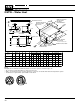
STEEL CONTROL
ENCLOSURE
22 1/4 x 11 1/8 x 6 1/2
SLIP & DRIVE
CONNECTION
C
D
W
COIL CLEANOUT
ACCESS
L*
4 1/2
Z
CONN ø, O.D.
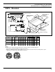
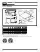
OPTIONAL MOUNTING
BRACKETS (FIELD
INSTALLED)
Q (MAX)
S = 5 1/2**
MODEL Q5 RADIATED
SOUND ELBOW
(OPTIONAL)
SEE DIMENSION K
*K MIN.
MOUNTING SURFACE
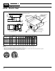
BLOWER
ACCESS
DOOR
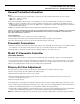
Notes
Weights are an estimate and will vary based on selection options, insulation type, etc.
• 36” clearance required by NEC for electrical enclosures.
• Add 1" to L dimension and **reduce dimension S to 4-1/2" for double wall and low temperature option.
• *K dimension required with optional Q5 sound elbow.
W
Model QPTW Size
Motor
H.P.
Cabinet
Size
Nominal
Inlet
Diameter
H
L
X
Z
Y
Discharge
1 ROW COIL
LB Z LB
Induction
CD
Min.
K
2 ROW COIL
CONN ø CONN ø
Q
1/2
34
11706, 11707, 11708, 11709
1/6
6,7,8,9
6,7,8,9
15
15
15
16
30
12-1/4
13-1/2
13 12
99 103
6
7/8
18
34
12506, 12507, 12508, 12509
1/4
1/6
1/4
15
17-1/2
17-1/2
17-1/2
16
30
13 12
13-1/2
12-1/4
102 106
6
7/8
1/2
18
18
18
40
40
40
21709, 21710, 21712
1/2
1/2
9,10,12
9,10,12
9,10,12
18
18
18
17-1/2
20
20
20
34
17
17
17
16
16
16
13-1/2
12-1/4
114
117
6
6
6
7/8
7/8
18
46
22509, 22510, 22512
3/4
20
17-1/2
24
34
21
18
13-1/2
12-1/4
119 122
8
7/8
7/8
20
46
46
25009, 25010, 25012
35012, 35014, 35016
37512, 37514, 37516
31012, 31014, 31016
1
12,14,16
12,14,16
12,14,16
20
20
17-1/2
34
40
40
40
24
24
21
21
18
18
13-1/2
13-1/2
13-1/2
13-1/2
12-1/4
12-1/4
12-1/4
12-1/4
124
154
159
166
127
160
165
172
8
8
7/8
7/8
7/8
7/8
7/8
7/8
7/8
7/8
20
20
1
1
2
2
2
3
3
3