
Manual


20
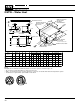
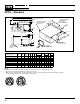
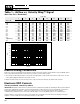
Table 1 – Airflow vs. Velocity Wing™ Signal
(Non-Flow Thru / Dead Head)
Inlet Size
678910121416
Sensor dP CFM
0.03 81 106 150 190 234 312 428 583
0.04 94 122 173 220 271 360 494 673
0.06 115 150 212 269 331 441 605 824
0.1 148 194 274 347 428 570 781 1064
0.2 210 274 388 491 605 806 1104 1505
0.3 257 335 475 601 741 987 1352 1844
0.4 297 387 548 694 856 1140 1562 2129
0.5 332 433 613 776 957 1274 1746 2380
0.6 363 474 672 851 1048 1396 1912 2607
0.7 392 512 725 919 1132 1508 2066 2816
0.8 419 547 775 982 1210 1612 2208 3011
0.9 445 581 823 1042 1284 1710 2342 3193
1 (K-Factor) 469 612 867 1098 1353 1802 2469 3366
1.5 574 750 1062 1345 1657 2207 3024 4122
Electric Analog Connections
Electronic controls are typically factory wired for single point power voltage supply with fan relay and 24VAC power
(from a step-down transformer) as part of the fan circuit or electric heater circuit.
1. The remote mounted thermostat is connected to the appropriate components located in the control box. See the
control wiring diagram affixed to the inside of cover.
2. When hot water reheat is used, the relay in the control box must be wired to the water valve actuator.
Electronic DDC Controls
(Factory-mounted, controls by others)
IMPORTANT All RS485 communication networks must be installed using twisted, shielded pair wiring. Each twisted
pair must be individually shielded. If using unshielded wiring, cables must be placed in solid metal conduit alone,
without DC switching or AC lines. Failure to use these types of connectors may result in various system
communication problems such as excessive network retries, noise susceptibility, and loss of communication.
If proper wiring is not used, the site may not meet FCC class A regulations for RFI emissions; thereby forcing the
installer or user to make the necessary wiring changes at a later date.
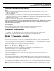
VelocityWingCalibration
10
100
1000
10000
0.01 0.1 1 10
SensordP
CFM
6
7
8
9
10
12
14
16
TM
50
500
Unit
S
iz
e
1.5
2000
5000
200
20