
Manual


24
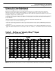
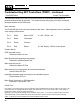
Table 4 – Unit Fan & Primary Flow Range Selection
Model QST (Note: Primary cfm may be reduced to the minimum controllable flow, but shall never exceed fan cfm.)
CFM
50
100
150
200
250
350
450
500
600
650
800
900
1000
1100
1200
1400
1600
1800
2000
2200
2300
2500
2600
Fan Flow Ranges
Inlet Primary Ranges
Min Fan Max Prim
Unit Size Inlet CFM & Fan
17 6 200 500
7 200 650
8 200 650
25 8 600 900
9 600 1100
10 600 1200
50 10 1000 1400
12 1000 1800
14 1000 1800
75 12 1200 2000
14 1200 2300
10 12 1600 2000
14 1600 2600
16 1600 2600
200
17
650
600
25
1200
1000
50
1800
1200
75
2300
1600
10
2600
450A
583P
16
2600
Note: Primary cfm may be reduced to the minimum controllable flow,
but shall never exceed fan cfm.
A Analog Controls
P Pneumatic Controls
45A
81P
6
470
70A
106P
7
610
90A
150P
8
835
115A
190P
9
1100
145A
234P
10
1355
155A
312P
12
1740
250A
428P
14
2300
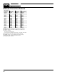
Table 5 – Unit Fan & Primary Flow Range Selection
Model EST
CFM
50
100
150
200
250
350
450
500
600
650
700
800
900
1000
1100
1200
1400
1600
1800
2000
2200
2400
2600
Fan Flow Ranges
Inlet Primary Ranges
Min Fan Max Prim
Unit Size Inlet CFM & Fan
33 8 175 810
9 175 1100
10 175 1100
50 10 450 1355
12 450 1600
14 450 1600
75 12 650 1800
14 650 2000
10 12 700 1800
14 700 2400
16 700 2400
175
33
1100
650
75
2000
Note: Primary cfm may be reduced to the minimum controllable flow,
but shall never exceed fan cfm.
A Analog Controls
P Pneumatic Controls
450A
583P
16
2600
45A
81P
6
470
70A
106P
7
610
90A
150P
8
835
115A
190P
9
1100
145A
234P
10
1355
155A
312P
12
1740
250A
428P
14
2300
700
10
2400
450
50
1600