Anetsberger Brothers, Inc. 180 North Anets Drive • Northbrook, Illinois 60062 • 847-272-0770 • Fax 847-272-1943 For ANETS Factory Warranty Service • 800-837-2638 FRYER Models 14G, 14GS 14GU, 14GSU, MX-14EG, MX-14EGU Installation, User Operation, & Maintenance Manual 14GS shown on standard 6” legs ! DANGER Improper installation, adjustment, alteration, service, or maintenance can cause property damage, injury or death.
! DANGER Read these specifications, Code Requirements, Installation Requirements, Installation Instructions, and Operating Instructions very carefully. Failure to follow the Instructions could cause the fryer to malfunction. A fryer malfunction can result in property damage, serious bodily injury, or death. CONTENTS Shipping Container Inspection ........................................................ 3 Fryer Gas Supply Specifications .....................................................
SHIPPING CONTAINER INSPECTION 1. Carefully examine the shipping carton for external damage. When damage is noted, notify the delivery carrier immediately. Save all packing materials for damage claim examination. 2. If no external damage is noted, remove the shipping carton from the fryer and examine the fryer carefully for damage. Place the fryer in a safe location, if damage is noted, so that the freight damage claims adjuster can examine the fryer. 3.
FRYER GAS SUPPLY SPECIFICATIONS Please make sure that your desired fryer location has gas supply factors that are suitable for this product: INPUT REQUIRED: 111,000 BTU* MANIFOLD PRESSURE SUPPLY PRESSURE*** Natural Gas Propane 3½“ W.C. ** 10“ W.C. 6“ W.C., minimum 11“ W.C., minimum * - BTU/Hr Rating is based on sea level operation. For sites above 2000 feet, reduce this rating 4% for each 1000 feet above sea level. ** - “W.C. = Inches, Water Column.
CODE REQUIREMENTS IMPORTANT: Read the Code Requirements and ALL installation instructions carefully, before starting the installation. Contact the factory if any problems or questions arise. The fryer installation must conform with local codes, or in the absence of local codes, with the National Fuel Gas Code, ANSI Z223.1 (latest edition); the Natural Gas Installation Code, CAN/ CGA-B149.1 (latest edition); or the Propane Gas Installation Code, CAN/CGA-B149.2 (latest edition), as applicable, including: a.
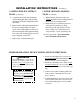
From the top of the flue on the fryer, allow a minimum of at least 10 inches vertical clearance beneath a ventilating hood. Figure 2. Fryer Site Installation Requirements INSTALLATION REQUIREMENTS Install the fryer in accordance with the preceding Code Requirements, as well as the following Installation Requirements. 1. DO NOT install this fryer in a mobile home, trailer, or recreational vehicle. 2.
INSTALLATION INSTRUCTIONS LEG INSTALLATION INSTRUCTIONS 1. Flatten the shipping carton (after unpacking the fryer and its parts and accessories) for surface protection during leg installation. LEG INSTALLATION INSTRUCTIONS (Continued) 7. Tighten the four locking nuts evenly and securely to hold the leg mounting plate against the fryer mounting bracket. 2. Position the side of the fryer flat on the carton, exposing the fryer bottom mounting brackets for leg installation, as shown in Figure 3. 3.
INSTALLATION INSTRUCTIONS (Continued) CASTER INSTALLATION INSTRUCTIONS 1. Flatten the shipping carton (after unpacking the fryer and its parts and accessories) for surface protection during leg installation. 2. Position the side of the fryer flat on the carton, exposing the fryer bottom mounting brackets for caster installation, as shown in Figure 4. 3. Place the caster mounting plate flush against the mounting bracket on the fryer bottom. 4.
INSTALLATION INSTRUCTIONS CASTER LEVELING INSTRUCTIONS (Continued) 5. Completely unscrew the bolts holding the caster mounting plate that requires leveling adjustment. Retain the locking nuts for later reassembly. 6. Reinsert each bolt through its flatwasher and the fryer mounting bracket; next, place a spacer of the required thickness on the bolt before inserting the bolt through its mounting hole on the caster mounting plate and screwing a locking nut onto the bolt.
GAS CONNECTION INSTRUCTIONS Installing your ANETS Fryer requires the following procedure, after its legs or casters are properly attached and it is in its desired location. 1. Ensure that the gas control valve knob in the fryer has its OFF position next to the valve mark. 2. Ensure that the gas supply inlet line valve is closed (cross-wise to the pipe line direction). 3. Ensure that all fryer controls are set to OFF. 4. Connect the ¾” gas supply line to the gas line adapter on the lower rear of the fryer.
FRYER OPERATING INSRUCTIONS ! CAUTION DO NOT attempt to operate this fryer during a interruption of gas service. Turn all fryer controls to OFF, including the gas control valve knob, then close the gas supply line valve. When notified that the gas interruption has ended, perform the Lighting Procedure (later in this manual). ! DANGER NEVER operate this fryer when its flue is blocked or when the ventilation hood is not on because the combustion products can cause injury to personnel.
FRYER OPERATING INSTRUCTIONS FRYER PREPARATION FOR USE “BOIL OUT” INSTRUCTIONS New ANETS Fryers are leak-tested and cleaned at the factory before shipping. Before using a newly installed fryer for food preparation, clean the kettle again, as follows: 1. Thoroughly wipe the interior of the kettle with clean cloths. Open the front door on the lower portion of the fryer to access the drain ball valve.
FRYER OPERATING INSTRUCTIONS (Continued) Normal operation of an ANETS Fryer requires that the kettle is filled with liquid shortening above the lower indent level, marked on the rear of the kettle, before lighting the fryer’s pilot and turning on the main burner. ! CAUTION: Shortening MUST be in liquid form to avoid scorching or discoloration and possible damage to the kettle. Damage caused by melting solid shortening will NOT be covered by the warranty.
FRYER OPERATING INSTRUCTIONS (Continued) SHUTDOWN PROCEDURE NOTE: Shutdown is recommended at the end of a workday or whenever no frying is required for a period of several hours. The fryer should be shutdown during any power outage or interruption of gas service. The fryer MUST also be shutdown before draining the kettle, or whenever there is no shortening in the kettle to prevent damage. 14 1. Turn the thermostat knob to OFF. 2.
FRYER OPERATING INSTRUCTIONS (Continued) RECOMMENDED FRYING TIME FOR POPULAR FRIED FOODS Load the fryer basket with the food product while the basket is not in the hot liquid shortening. DO NOT overload the fryer basket. Load only a premeasured quantity of food product (1½ lb, typically; less, if smaller portions are desired). Place the loaded fryer basket into the hot liquid shorteningcarefully to avoid splashing.
FRYER OPERATING INSTRUCTIONS DAILY CLEANING PROCEDURE DAILY CLEANING PROCEDURE NOTE: Cleaning is recommended at the end of a workday, to prepare the fryer for proper operation the next time it is to be used. (Continued) 5. Allow the shortening to cool before draining. Slowly open the drain ball valve to drain the shortening. Take care to avoid spilling or splashing the shortening. ! DANGER DO NOT move the fryer while it contains HOT shortening.
FRYER OPERATING INSTRUCTIONS (Continued) DAILY CLEANING PROCEDURE (Continued) 12. Return the screen (or, if used, the sediment tray) to its proper position in the kettle. Place the fryer baskets on the basket hanger, ready for use. 13. Perform the Lighting Procedure to return the fryer to operation, when desired. MONTHLY MAINTENANCE INSTRUCTIONS NOTE: Regular maintenance is recommended to keep the fryer operating properly.
FRYER TROUBLESHOOTING GUIDE All service (repairs or part replacement) must be performed by a qualified Service Agency. PROBLEM Pilot (piezo-electric) pushbutton igniter, if present, does not light the pilot flame Pilot flame does not stay lighted. 18 CAUSE REMEDY 1. Electrode of igniter out of position or dirty/sooty electrode. 1. Move electrode within 3/16” of pilot burner tip. Clean the electrode. 2. Loose spark wire; loose igniter nut. 2.
FRYER TROUBLESHOOTING GUIDE PROBLEM CAUSE Pilot flame does not 6. High-limit thermostat problem has shut off stay lighted. (Continued) the gas. (Continued) (Continued) REMEDY 6. (Continued) For model 14GS, MX-14EG, and MX14-EGU fryers ONLY: Test the high-limit thermostat by disconnecting the thermocouple at the gas control valve. Then, disconnect the red wires to the high-limit thermostat from the gas control valve.
FRYER TROUBLESHOOTING GUIDE PROBLEM Pilot flame goes out repeatedly. (Continued) CAUSE 4. High-limit thermostat problem has shut off the gas. (Continued) (Continued) REMEDY 4. (Continued) For model 14GS, MX-14EG, and MX14-EGU fryers ONLY: Test the high-limit thermostat by disconnecting the thermocouple at the gas control valve. Then, disconnect the red wires to the high-limit thermostat from the gas control valve.
FRYER TROUBLESHOOTING GUIDE PROBLEM Main burners do not stop burning. Liquid shortening does not reach the desired temperature for frying. CAUSE (Continued) REMEDY 1. Thermostat has failed. 1. Turn the thermostat control knob to OFF. If the burners do not quit burning, the thermostat has failed and must be replaced. 2. Gas control valve has failed. 2. Turn the gas control valve knob to OFF. If the burners do not quit burning, the gas control valve has failed and must be replaced. 1.
FRYER TROUBLESHOOTING GUIDE PROBLEM CAUSE Liquid shortening does 3. Loose knob on thermostat; or thermostat not reach the desired requires calibration (temperature setting temperature for frying. differs by about 10°F from measured (Continued) shortening temperature). (Continued) (Continued) REMEDY 3. (Continued) the shortening temperature has stabilized. Measure the temperature of the shortening by inserting an accurate thermometer about 4 inches into the shortening to measure its temperature.
LIMITED WARRANTY ANETSBERGER BROTHERS, INC., Northbrook, Illinois, USA, certifies that all equipment of its manufacture is, to the best of its knowledge, free from defective material and workmanship. ANETSBERGER BROTHERS, INC., agrees to replace any integral part of its equipment that proves defective within 15 months of date of original shipment from the factory, or 12 months from the date of installation, whichever is sooner.
Anetsberger Brothers, Inc. 180 North Anets Drive • Northbrook, Illinois 60062 • 847-272-0770 • Fax 847-272-1943 Toll-free Customer & Warranty Service: 800/ 837-2638 www.anetsberger.com Keep this Manual in a Convenient Location for Reference Form I-102; Rev. 10/01 Price $20.