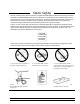
Caution Do not exceed the operating input power level, voltage level, current level, and signal type that is appropriate for the instrument being used. Refer to your instrument’s operation manual for safe operating practices and device limitations. Electrostatic Discharge (ESD) can damage the highly sensitive circuits in the instrument. ESD is most likely to occur as test devices are being connected to, or disconnected from, the instrument’s front and rear panel ports and connectors.
MS462XX VECTOR NETWORK MEASUREMENT SYSTEM OPERATION MANUAL TIP TO GET STARTED QUICKLY Read the companion MS462XX Measurement Guide (PN: 10410-00213) for a system overview along with detailed help for calibration, applications, features, and software system support. 490 JARVIS DRIVE l MORGAN HILL, CA 95037-2809 P/N: 10410-00203 REVISION: N PRINTED: SEPTEMBER 2005 COPYRIGHT 2005 ANRITSU CO.
WARRANTY The Anritsu product(s) listed on the title page is (are) warranted against defects in materials and workmanship for three years from the date of shipment. Anritsu’s obligation covers repairing or replacing products which prove to be defective during the warranty period. Buyers shall prepay transportation charges for equipment returned to Anritsu for warranty repairs. Obligation is limited to the original purchaser. Anritsu is not liable for consequential damages.
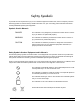
Safety Symbols To prevent the risk of personal injury or loss related to equipment malfunction, Anritsu Company uses the following symbols to indicate safety-related information. For your own safety, please read the information carefully BEFORE operating the equipment. Symbols Used in Manuals DANGER This indicates a very dangerous procedure that could result in serious injury or death if not performed properly.
For Safety WARNING Always refer to the operation manual when working near locations where the alert mark, shown on the left, is attached. If the operation, etc., is performed without heeding the advice in the operation manual, there is a risk of personal injury. In addition, the equipment performance may be reduced. Moreover, this alert mark is sometimes used with other marks and descriptions indicating other dangers.
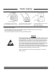
Static Safety Anritsu products comply with the immunity requirements defined by the European Immunity Standard EN 61000-4-2:1995/EN50082-1:1997-4kV CD, 8kV AD for static discharge. This standard requires that the products survive air discharge static levels of 8 kV, and direct contact discharge static levels of 4 kV. The standard also states, "the static electricity discharges shall be applied only to such points and surfaces of the equipment which are accessible to personnel during normal usage.
Static Safety 7. Handle PCBs only by their edges. Do not handle by the edge connectors. 8. Lift & handle solid state devices by their bodies—never by their leads. 9. Transport and store PCBs and other static sensitive devices in static-shielded containers. ADDITIONAL PRECAUTIONS Keep work spaces clean and free of any objects capable of holding or storing a static charge. Connect soldering tools to an earth ground. Use only special anti-static suction or wick-type desoldering tools.
Narrative Table of Contents Chapter 1 — General Information This chapter provides a general description of the Anritsu Model MS462XX Vector Network Measurement System. It also provides descriptions for the precision component kits, and equipment options. Chapter 2 — Installation This chapter provides instructions for performing an initial inspection, preparing the equipment for use, setting up for operation over the IEEE-488.2 (GPIB) Bus, using a printer, and preparing the units for storage and/or shipment.
Narrative Table of Contents (Continued) Chapter 11 — Calibration Kits This chapter provides a description and listing of components for the calibration kits. Appendix A — Sequence Operation This appendix describes the Seq (Sequence) key function and provides procedures for its use. Appendix B — Model MS462XX VNMS Rear Panel Connectors This appendix describes the rear panel connectors. It also provides pinout listings.
Table of Contents Chapter 1 General Information 1-1 SCOPE OF MANUAL . . . . . . . . . . . . . . . . . . . . . . . . . . . . . . . . . 1-3 1-2 INTRODUCTION . . . . . . . . . . . . . . . . . . . . . . . . . . . . . . . . . . . 1-3 1-3 SERIAL NUMBER. . . . . . . . . . . . . . . . . . . . . . . . . . . . . . . . . . . 1-3 1-4 ONLINE MANUALS. . . . . . . . . . . . . . . . . . . . . . . . . . . . . . . . . . 1-3 1-5 RELATED MANUALS AND LITERATURE . . . . . . . . . . . . . . . . . . . . .
Table of Contents (Continued) 2-9 PREPARATION FOR STORAGE AND/OR SHIPMENT. . . . . . . . . . . . . . . 2-7 Preparation for Storage . . . . . . . . . . . . . . . . . . . . . . . . . . . . . . 2-7 Preparation for Shipment . . . . . . . . . . . . . . . . . . . . . . . . . . . . . 2-7 2-10 SERVICE CENTERS . . . . . . . . . . . . . . . . . . . . . . . . . . . . . . . . . 2-9 Chapter 3 Network Analyzers, A Primer 3-1 INTRODUCTION . . . . . . . . . . . . . . . . . . . . . . . . . . . . . . . . . . .
Table of Contents (Continued) Chapter 5 Error and Status Messages 5-1 INTRODUCTION . . . . . . . . . . . . . . . . . . . . . . . . . . . . . . . . . . . 5-3 5-2 ERROR MESSAGES. . . . . . . . . . . . . . . . . . . . . . . . . . . . . . . . . . 5-3 Chapter 6 Data Displays 6-1 INTRODUCTION . . . . . . . . . . . . . . . . . . . . . . . . . . . . . . . . . . . 6-3 6-2 DISPLAY MODES AND TYPES . . . . . . . . . . . . Single Channel Display— Ch 1, 2, 3, 4 . . . . . . .
Table of Contents (Continued) 7-4 MEASUREMENT CALIBRATION—SLIDING TERMINATION . . . . . . . . . 7-13 7-5 STANDARD 2-PORT (OSL) CALIBRATION PROCEDURE . . . . . . . . . . . . 7-19 7-6 TRANSMISSION AND REFLECTION 3-PORT CALIBRATION . . . . . . . . . 7-23 7-7 FOUR-PORT CALIBRATION . . . . . . . . . . . . . . . . . . . . . . . . . . . . 7-26 7-8 LRL/LRM CALIBRATION PROCEDURE. . . . . . . . . . . . . . . . . . . . . . 7-27 7-9 TRM CALIBRATION PROCEDURE . . . . . . . . . . . . . . . . . . . . . . . .
Table of Contents (Continued) 10-5 MS462XA/B NON-RATIO PARAMETERS TEST . . . . . . . . . . . . . . . . . . 10-5 10-6 MS462XA/B HIGH LEVEL NOISE TEST . . . . . . . . . . . . . . . . . . . . . 10-10 10-7 MS462XC SYSTEM DYNAMIC RANGE TEST . . . . . . . . . . . . . . . . . . 10-17 Chapter 11 Calibration Kits 11-1 INTRODUCTION. . . . . . . . . . . . . . . . . . . . . . . . . . . . . . . . . . . 11-3 11-2 PURPOSE. . . . . . . . . . . . . . . . . . . . . . . . . . . . . . . . . . . . . . .
Table of Contents (Continued) A-18 TTL OUTPUT FOR CONTROLLING PERIPHERALS . . . . . . . . . . . . . . A-18 A-19 TTL INPUT CONTROL STATEMENT . . . . . . . . . . . . . . . . . . . . . . . A-19 A-20 BNC TTL OUTPUT CONTROL STATEMENT . . . . . . . . . . . . . . . . . . . A-20 A-21 GOSUB SEQUENCE . . . . . . . . . . . . . . . . . . . . . . . . . . . . . . . . A-21 A-22 NESTING GOSUB SEQUENCES. . . . . . . . . . . . . . . . . . . . . . . . . . A-22 A-23 OPERATOR MESSAGES . . . . . . . . . . . . . . . .
Chapter 1 General Information Table of Contents 1-1 SCOPE OF MANUAL . . . . . . . . . . . . . . . . . . . . . . . . . . . . . . . . . 1-3 1-2 INTRODUCTION . . . . . . . . . . . . . . . . . . . . . . . . . . . . . . . . . . . 1-3 1-3 SERIAL NUMBER. . . . . . . . . . . . . . . . . . . . . . . . . . . . . . . . . . . 1-3 1-4 ONLINE MANUALS. . . . . . . . . . . . . . . . . . . . . . . . . . . . . . . . . . 1-3 1-5 RELATED MANUALS AND LITERATURE . . . . . . . . . . . . . . . . . . . . .
Figure 1-1.
Chapter 1 General Information 1-1 SCOPE OF MANUAL This manual provides general information, installation, and operating information for the MS4622, MS4623, and MS4624 A, B, C, and D models Vector Network Measurement System (VNMS). (Throughout this manual, the terms MS462XX VNMS and MS462XX will be used interchangeably to refer to the system.) Manual organization is shown in the table of contents.
EXTERNAL INTERFACES GENERAL INFORMATION Table 1-1.
GENERAL INFORMATION PRECISION COMPONENT KITS NOTES The MS462XC VNMS- Direct Receiver Access version cannot make system measurements without an external test set that couples power into the reference and test channels, such as the Anritsu MS4782A. This manual will discuss calibration and system measurements for the MS462XX assuming the user understands the need for the external test set for the MS462XC.
PRECISION COMPONENT KITS 1-8 PRECISION COMPONENT KITS GENERAL INFORMATION Two types of precision-component kits are available: calibration and verification. Calibration kits contain components used to identify and separate error sources inherent in microwave test setups. Details of these kits are described in the following paragraphs. 3750R The 3750R Calibration Kit (Figure 1-2) contains Calibration Kit precision 3.5 mm components with characteristics that are traceable to the NIST.
GENERAL INFORMATION PRECISION COMPONENT KITS 3753R The 3753R Calibration Kit (Figure 1-4) contains Calibration Kit precision Type N components with characteristics that are traceable to the NIST. Used primarily by the metrology laboratory, these components provide the most dependable means of determining system accuracy.
OPTIONS 1-9 1-10 1-8 OPTIONS PERFORMANCE SPECIFICATIONS GENERAL INFORMATION The following options are available.
GENERAL INFORMATION 1-11 PREVENTIVE MAINTENANCE PREVENTIVE MAINTENANCE The MS462XX VNMS requires periodic cleaning of the cooling fan screen to prevent an obstruction that could facilitate overheating. Additional maintenance that may be required includes replacing a blown fuse, replacing the CPU backup battery, and replacing the LCD backlight. This additional maintenance is outlined below: Fuses The MS462XX contains three fuses, two internal and one external.
CONVENTIONS 1-12 CONVENTIONS GENEERAL INFORMATION Throughout this manual, path names may be used to represent the keystrokes for a desired action or procedure. The pathname begins with a front panel key selection, followed by additional front panel or softkey selections, each separated by a forward slash (/). Front panel key names and soft keys are presented in the manual as they are on the system, that is, in initial caps or all uppercase letters as appropriate.
Chapter 2 Installation Table of Contents 2-1 INTRODUCTION . . . . . . . . . . . . . . . . . . . . . . . . . . . . . . . . . . . 2-3 2-2 INITIAL INSPECTION . . . . . . . . . . . . . . . . . . . . . . . . . . . . . . . . 2-3 2-3 PREPARATION FOR USE . . . . . . . . . . . . . . . . . . . . . . . . . . . . . . 2-3 2-4 GPIB SETUP AND INTERCONNECTION. . . . . . . . . . . . . . . . . . . . . . 2-4 Interface Connector. . . . . . . . . . . . . . . . . . . . . . . . . . . . . . . . .
Chapter 2 Installation 2-1 INTRODUCTION This chapter provides information for the initial inspection and preparation for use of the MS462XX Vector Network Measurement System. Information for interfacing the MS462XX to the IEEE-488 General Purpose Interface Bus and reshipment and storage information is also included. 2-2 INITIAL INSPECTION Inspect the shipping container for damage.
GPIB SETUP AND INTERCONNECTION 2-4 GPIB SETUP AND INTERCONNECTION INSTALLATION All functions of the MS462XX (except power on/off and initialization of the hard disk) can be controlled remotely by an external computer/controller via the IEEE-488.2 GPIB. The information in this section pertains to interface connections and cable requirements for the rear panel GPIB connector.
INSTALLATION 2-5 SYSTEM GPIB INTERCONNECTION SYSTEM GPIB INTERCONNECTION There are two rear panel GPIB IEEE-488 connectors. The IEEE 488.2 connector is used to interface the MS462XX to an external computer/ controller via a standard GPIB cable. The dedicated GPIB connector is used to interface to plotters and an external source for multiple source operation via a standard GPIB cable.
PREPARATION FOR STORAGE AND/OR SHIPMENT INSTALLATION Inappropriate setting of the Default Gateway IP Address will cause the Scorpion system to appear to be locked up at start up.
INSTALLATION PREPARATION FOR STORAGE AND/OR SHIPMENT the kit). Orient the handles such that the slotted opening in the handle mounting plate (Figure 2-1) is toward the bottom of the unit. Slotted Opening Figure 2-1. Rack Mount Handle Showing Slotted Opening Step 6. For Option 1, install the rack mount assembly to the front and rear using the green-headed screws removed earlier (or use the ones from the kit).
SERVICE CENTERS INSTALLATION Use a Suitable Container Obtain a corrugated cardboard carton with a 275-pound test strength. This carton should have inside dimensions of no less than six inches larger than the instrument dimensions to allow for cushioning. Protect the Instrument Surround the instrument with polyethylene sheeting to protect the finish. Cushion the Instrument Cushion the instrument on all sides by tightly packing dunnage or urethane foam between the carton and the instrument.
INSTALLATION 2-10 SERVICE CENTERS SERVICE CENTERS A list of Anritsu worldwide Service Centers is provided in Table 2-1. Table 2-1. Anritsu Service Centers UNITED STATES FRANCE JAPAN ANRITSU COMPANY 490 Jarvis Drive Morgan Hill, CA 95037-2809 Telephone: (408) 776-8300 1-800-ANRITSU FAX: 408-776-1744 ANRITSU S.A 9 Avenue du Quebec Zone de Courtaboeuf 91951 Les Ulis Cedex Telephone: 016-09-21-550 FAX: 016-44-61-065 ANRITSU CUSTOMER SERVICES LTD. 1800 Onna Atsugi-shi Kanagawa-Prf.
Chapter 3 Network Analyzers, A Primer Table of Contents 3-1 INTRODUCTION . . . . . . . . . . . . . . . . . . . . . . . . . . . . . . . . . . . 3-3 3-2 GENERAL DESCRIPTION . . Source Module or Modules . Test Set Module . . . . . . Analyzer Module . . . . . . 3-3 NETWORK ANALYZERS . . . . . . . . . . . . . . . . . . . . . . . . . . . . . . . 3-5 Scalar Analyzer Comparison . . . . . . . . . . . . . . . . . . . . . . . . . . . . 3-5 Vector Network Measurement System Basics . . . . . . . . . . . . . . . . .
Chapter 3 Network Analyzers, A Primer 3-1 3-2 INTRODUCTION GENERAL DESCRIPTION This section provides front panel operating and measurement application information and data. It includes discussions on the following topics: q System description q General discussion about network analyzers q Basic measurements and how to make measurements q Error correction The Model MS462XX Vector Network Measurement System measures the magnitude and phase characteristics of networks that include passives (e.g.
GENERAL DESCRIPTION NETWORK ANALYZERS, A PRIMER INCIDENT TEST DEVICE TERMINATION REFLECTED Return Loss (dB) Reflection Coefficients (S11, S22) Reflection Coefficients vs Distance (Fourier Transform) Impedance (R + j X) SWR Figure 3-2. Reflection Measurements The MS462XX is a self-contained, fully integrated measurement system that includes an optional time domain capability.
NETWORK ANALYZERS, A PRIMER NETWORK ANALYZERS Analyzer Module 3-3 NETWORK ANALYZERS SCALAR NETWORK ANALYZERS MICROWAVE SIGNAL MICROWAVE DETECTOR DETECTOR OUTPUT VOLTAGE DETECTOR OUTPUT VOLTAGE IS PROPORTIONAL TO SIGNAL AMPLITUDE. Figure 3-3. Scalar Analyzer Detection The analyzer module down-converts, receives, and interprets the IF signal for phase and magnitude data. It then displays the results of this analysis on a color display. This display can show all four S-parameters simultaneously.
NETWORK ANALYZERS NETWORK ANALYZERS, A PRIMER A NETWORK ANALYZER IS A TUNED RECEIVER INTERMEDIATE FREQUENCY (IF) MICROWAVE SIGNAL frequency (IF). This signal can then be measured directly by a tuned receiver. The tuned receiver approach gives the system greater dynamic range. The system is also much less sensitive to interfering signals, including harmonics. Vector Network The network measurement system is a tuned receiver (Figure 3-5, left).
NETWORK ANALYZERS, A PRIMER NETWORK ANALYZERS analyzer would measure a phase difference of 0 degrees. REFERENCE SIGNAL TEST SIGNAL PHASE DETECTOR MICROWAVE SOURCE SPLITTER LONGER BY ONE WAVELENGTH LENGTH (360 degrees) Now consider that we make this same measurement at 1.1 GHz. The frequency is higher by 10 percent so therefore the wavelength is shorter by 10 percent. The test signal path length is now 0.1 wavelength longer than that of the reference signal (Figure 3-9). This test signal is: 1.
MEASURED PHASE NETWORK ANALYZERS NETWORK ANALYZERS, A PRIMER There are two ways of accomplishing this. The most obvious way is to insert a length of line into the reference signal path to make both paths of equal length (Figure 3-11, below). With perfect transmission lines and a perfect splitter, we would then measure a constant phase as we change the frequency. The problem using this approach is that we must change the line length with each measurement setup. +180 +90 0 1.1 1.2 1.3 1.
NETWORK ANALYZERS, A PRIMER NETWORK ANALYZERS Network Analyzer Measurements PORT 1 FORWARD REFLECTION PORT 2 DUT REVERSE REFLECTION Figure 3-14. Forward and Reverse Measurements S21 FORWARD TRANSMISSION PORT 1 S11 FORWARD REFLECTION PORT 2 DUT S22 REVERSE REFLECTION S12 REVERSE TRANSMISSION Figure 3-15. S-Parameters PHASE +180 0 -180 FREQUENCY Now let us consider measuring the DUT. Consider a two port device; that is, a device with a connector on each end.
NETWORK ANALYZERS NETWORK ANALYZERS, A PRIMER POLAR DISPLAY 90 180 0 -90 Figure 3-17. Polar Display SMITH CHART INDUCTIVE 50 CAPACITIVE Figure 3-18. Smith Chart There are several ways in which all the information can be displayed on one trace. One method is a polar display (Figure 3-17). The radial parameter (distance from the center) is magnitude. The rotation around the circle is phase.
NETWORK ANALYZERS, A PRIMER NETWORK ANALYZERS Another important parameter we can measure when phase information is available is group delay. In linear devices, the phase change through the DUT is linear-with-frequency. Thus, doubling the frequency also doubles the phase change. An important measurement, especially for communications system users, is the rate of change-of-phase-vs.-frequency (group delay). If the rate of phase-change-vs.-frequency is not constant, the DUT is nonlinear.
NETWORK ANALYZERS NETWORK ANALYZERS, A PRIMER Summary 3-12 A network analyzer is similar to a scalar network analyzer. The major difference it that it adds the capability for measuring phase as well as amplitude. With phase measurements comes scattering, or S-parameters, which are a shorthand method for identifying forward and reverse transmission and reflection characteristics. The ability to measure phase introduces two new displays, polar and Smith Chart.
Chapter 4 Front Panel Operation Table of Contents 4-1 INTRODUCTION . . . . . . . . . . . . . . . . . . . . . . . . . . . . . . . . . . . 4-3 4-2 FRONT PANEL KEY DESCRIPTIONS . . . . . . . . . . . . . . . . . . . . . . . 4-3 4-3 SOFT-KEY MENUS, GENERAL . . . . . . . . . . . . . . . . . . . . . . . . . . . 4-6 4-4 APPL KEY MENUS . . . . . . . . . . . . . . . . . . . . . . . . . . . . . . . . . . 4-7 4-5 MEAS KEY MENUS . . . . . . . . . . . . . . . . . . . . . . . . . . . . . . . . .
20 MS4623B 18 19 Vector Network Measurement System 10 MHz-6 GHz Data Entry 7 8 9 G/ns/m 4 5 6 M/m s/cm 1 2 3 k/ms/mm 0 . - X1 Enter Clr Local Channels Enhancement Appl Ch 1 Ch 2 Seq Cal Ch 3 Ch 4 Avg Utility Meas Display Stimulus Port 3 Power 1 2 System Marker Freq Sweep Print Hard Copy Hold Power Config Default Save / Recall Port 1 Port 2 Keyboard Probe Power 3 Figure 4-1.
Chapter 4 Front Panel Operation 4-1 4-2 INTRODUCTION This chapter describes the front panel keys, controls, menus, and related GPIB mnemonics. The chapter is organized into an overall description of the front panel key-groups and detailed descriptions of individual keys within the key-groups. FRONT PANEL KEY DESCRIPTIONS The following pages provide descriptions of the front panel key-groups indexed in Figure 4-1. Index 1 Ground connector: Index 2 Power: Turns the MS462XX on and off.
FRONT PANEL KEY DESCRIPTIONS Index 12 FRONT PANEL OPERATION Stimulus Keys Freq: Displays the first in a series of menus that provide frequency-sweep control and let you trigger I.F. calibration measurements. See page 4-62. Sweep: Displays the first in a series of soft-key menus that provide frequency-sweep control. See page 4-65. Power: Displays the first in a series of menus that provide RF power control. See page 4-70.
FRONT PANEL OPERATION Index 16 FRONT PANEL KEY DESCRIPTIONS System Keys Print: Tells the printers, plotters or disk files to start output based on the current selections. Hard Copy: Displays the first in a series of menus that let you define and perform hard-copy output functions to printers, plotters or disk files. See page 4-108. Default: Displays a menu that lets you return the MS462XX front panel to its default settings. See page 4-115.
FRONT PANEL KEY DESCRIPTIONS FRONT PANEL OPERATION b. GPIB Mode: The key returns the instrument to local (front panel) control, unless the controller has sent a local lockout message (LLO) over the bus. 4-3 4-6 Index 19 Diskette Drive: Provides for the 3.5-inch, high-density (1.44 MB) floppy diskette used to store selected front panel setups and calibrations. Index 20 CRT Display: Displays any or all of the four measurement channels, plus soft-key menus.
FRONT PANEL OPERATION 4-4 APPL KEY MENUS APPL KEY MENUS Menu Name This key provides entry to measurement application functions. Function MEASUREMENT TYPE XXXX Description Changes the soft-key display to the MEASUREMENT TYPE menu. APPX? Selects device type to be non-mixer. APPDEVS DEVICE TYPE APPLICATIONS STANDARD MIXER GPIB Mnemonic APPDEVX? Selects device type to be mixer. APPDEVM ENTRY STATE CURRENT/PREVIOUS Switches between current and previous application entry states.
APPL KEY MENUS Menu Name D.C. TERM SETUP FOR LOWPASS PROCESSING FRONT PANEL OPERATION Function Description AUTO EXTRAPOLATE Sets the D.C. term to a value determined by extrapolating the data points near the zero frequency. DCA; DCX? LINE IMPEDANCE Sets the D.C. term to the characteristic impedance of the transmission medium (Z0). DCZ OPEN Sets the D.C. term to correspond to an open circuit. DCO SHORT Sets the D.C. term to correspond to a short circuit. DCS OTHER XXX.XXX Sets the D.C.
FRONT PANEL OPERATION Menu Name DOMAIN2 ENR TABLE OPERATION FREQUENCY TRANSLATION GROUP DELAY APPL KEY MENUS Function Description GPIB Mnemonic RANGE SETUP Changes the soft-key display to a DISPLAY SETUP menu. None GATE SETUP Changes the soft-key display to the GATE SETUP menu. None SELECT GATE FUNCTION None OFF Switches gate function Off. GOF DISPLAY Switches gate function to Display. GDS ON Switches gate function ON. GON HELP ON/OFF Displays an informational help screen.
APPL KEY MENUS Menu Name HARMONIC FRONT PANEL OPERATION Function Description SWEEP MODE SOURCE/CW RCVR Sweeps the source frequency or receiver frequency. APPSWPC; APPSWPS; APPSWPX? PORT 1,2/1,3 Selects Port 1, Port 2, or Port 3 as the second port. HARP12; HARP13; HARPX? HARMONIC SETUP Changes the soft-key display to the HARMONIC SETUP menu. None HELP ON/OFF Displays an informational help screen.
FRONT PANEL OPERATION Menu Name IMD SOURCE SELECTION INTERMODULATION DISTORTION LOAD ENR TABLE APPL KEY MENUS Function Description GPIB Mnemonic SELECTOR MODE DEFINE/APPLY Switches between DEFINE and APPLY setup modes. The parameter changes selected below are not applied to the hardware while in DEFINE mode. IMDSSMD; IMDSSMA; IMDSSMX? TONE 1 IS SOURCE (1-4)X Selects Tone 1 source. IMDT1S1-IMDT1S4; IMDT1SX? TONE 2 IS SOURCE (1-4)X Selects Tone 2 source.
APPL KEY MENUS Menu Name FRONT PANEL OPERATION Function GPIB Mnemonic START XXX.XXX mm Sets the start distance of the display. GST; GST? STOP XXX.XXX mm Sets the stop distance of the display. GSP; GSP? CENTER XXX.XXX mm Sets the center distance of the display. GCT; GCT? Sets the span (Stop - Start) distance of the display. GSN; GSN? SPAN LOWPASS XXX.XXX mm DISTANCE RESPONSE DISPLAY SETUP IMPULSE/STEP Switches between Impulse and Step response.
FRONT PANEL OPERATION Menu Name APPL KEY MENUS Function GPIB Mnemonic TRANSMISSION AND REFLECTION Changes the soft-key display to the TRANSMISSION AND REFLECTION menu or to the MIXER TRANSMISSION AND REFLECTION menu, if MIXER is the measurement type. APPTR NOISE FIGURE Changes the soft-key display to the NOISE FIGURE menu or to MIXER NOISE FIGURE menu, if MIXER is the measurement type. APPNF Changes the soft-key display to the HARMONIC menu.
APPL KEY MENUS Menu Name MIXER LO/RECEIVER SETUP FRONT PANEL OPERATION Function Description GPIB Mnemonic LO IS SOURCE (2 - 4) X Selects the LO source. APPLORS2-APPLORS4; APPLORSX? LO OFFSET FROM RF +/- XXX.XXXXXXXX GHz Sets the offset of LO from RF frequency, which is set in the FREQUENCY menu. APPLOROFF; APPLOROFF? LO CW ON/OFF MODE Toggles the LO CW mode on or off. If the LO MODE is on, the LO OFFSET is not displayed. APPLORCW1; APPLORCW0; APPLORCWX? LO CW FREQUENCY XXX.
FRONT PANEL OPERATION Menu Name APPL KEY MENUS Function Description TEST AUT Changes the soft-key display to the MULTIPLE FREQUENCY GAIN COMPRESSION2 menu. None TEXT DATA TO HARD DISK Changes the soft-key display to the SELECT FILE TO OVERWRITE menu. None TEXT DATA TO FLOPPY DISK Changes the soft-key display to the SELECT FILE TO OVERWRITE menu. None Toggles the FIXED SCALE mode on or off. GCFSON; GCFSOFF; GCFS? Enter the Y start power level for multiple frequency gain compression.
APPL KEY MENUS Menu Name NOISE FIGURE SETUP FRONT PANEL OPERATION Function Description GPIB Mnemonic NOISE SOURCE INTERNAL/EXTERNAL Toggles noise source between Internal and External. NFSRCI; SFSRCE; NFSRCE; NFSRCX? COLD TEMPERATURE XXX.XXX K Selects Noise Figure Cold Temperature. NFCT; NFCT? WIDEBAND BW CORR FREQ XXXXXXXX MHz Displays wideband correction frequency. NFBW; NFBW? WIDEBAND BW CORR MODE ON/OFF This menu item only displays if wideband mode is on.
FRONT PANEL OPERATION Menu Name APPL KEY MENUS Function NOMINAL OFFSET XXX dB Description GPIB Mnemonic Sets nominal offset. NOFST; NOFST? Sets gain compression point. GCMP; GCMP? Changes the soft-key display to the TEST SIGNALS menu. SFGCT Displays an informational help screen. HELP1; HELP0; HELPX? RETURN TO T/R MODE Changes the soft-key display to the TRANSMISSION AND REFLECTION menu. UNDOGC SET FREQUENCIES Changes the soft-key display to the SWEPT POWER GAIN COMPRESSION2 menu.
APPL KEY MENUS Menu Name FRONT PANEL OPERATION Function SWEPT POWER FREQUENCY XXX.XXXXXX GHz Description Sets the power sweep frequency. GPIB Mnemonic PSF; PSF? P START XX.XX dBm Displays the sweep start power. PSTRT? P STOP XX.XX dBm Displays the sweep stop power. PSTOP? Displays the power sweep step size. PSTEP? Toggles the power sweep on or off. PSWP1; PSWP0; PSWPX? MULTIPLE FREQ GAIN COMPRESSION Changes the soft-key display to the MULTIPLE FREQUENCY GAIN COMPRESSION menu.
FRONT PANEL OPERATION Menu Name APPL KEY MENUS Function Description GPIB Mnemonic RECTANGULAR Selects a Rectangular (one-term) shape. NOMINAL Selects a two-term Hamming shape. WNM; GNM Selects a three-term Blackman-Harris shape. WLS; GLS Selects a four-term Blackman-Harris shape. WMS; GMS HELP ON/OFF Displays an informational help screen. HELP1; HELP0; HELPX? RETURN Returns to the previous soft-key menu.
MEAS KEY MENUS 4-5 FRONT PANEL OPERATION MEAS KEY MENUS Menu Name SELECT BALANCED PORT PAIR Function Description GPIB Mnemonic (1:2)/(2:1) Selects Ports 1:2 or 2:1 as the balanced port pair for MM1P12; MM1P21; the active channel. MM1P? (1:3)/(3:1) Selects Ports 1:3 or 3:1 as the balanced port pair for MM1P13; MM1P31; the active channel. MM1P? (2:3)/(3:2) Selects Ports 2:3 or 3:2 as the balanced port pair for MM1P23; MM1P32; the active channel.
FRONT PANEL OPERATION Menu Name MEAS KEY MENUS Function Description GPIB Mnemonic (1:2)/(2:1) Selects Ports 1:2 or 2:1 as the second balanced port MM2P12; MM2P21; pair for the active channel. MM2P? (1:3)/(3:1) Selects Ports 1:3 or 3:1 as the second balanced port MM2P13; MM2P31; pair for the active channel. MM2P? (2:3)/(3:2) Selects Ports 2:3 or 3:2 as the second balanced port MM2P23; MM2P32; pair for the active channel.
MEAS KEY MENUS Menu Name FRONT PANEL OPERATION Function Description GPIB Mnemonic SDC MODE CONVERSION Selects SDC to be the active S-parameter. MSDC; MMSDC* SCD Selects SCD to be the active S-parameter. MSCD; MMSCD* SELECT BALANCED PORT PAIR* (SDS):(2:3)1 Changes the soft-key display to the appropriate SELECT BALANCED PORT PAIR menu.
FRONT PANEL OPERATION Menu Name MEAS KEY MENUS Function (4 OR 3 PORT MODELS WITH OPTION 24) SELECT S-PARAMETER GPIB Mnemonic SD2C1 MODE CONVERSION Selects SD2C1 to be the active S-parameter. MSD2C1; MMSD2C1 SD2C2 MODE CONVERSION Selects SD2C2 to be the active S-parameter. MSD2C2; MMSD2C2 SC1D1 MODE CONVERSION Selects SC1D1 to be the active S-parameter. MSC1D1; MMSC1D1 Selects SC1D2 to be the active S-parameter. MSC1D2; MMSC1D2 Selects SC2D1 to be the active S-parameter.
MEAS KEY MENUS Menu Name FRONT PANEL OPERATION Function Description GPIB Mnemonic S13, TRANS/USER 5 b1/a3 Selects S13 to be the active S-parameter. S13 S23, TRANS/USER 6 b2/a3 Selects S23 to be the active S-parameter. S23 S31, TRANS/USER 7 b3/a1 Selects S31 to be the active S-parameter. S31 S32, TRANS/USER 8 b3/a2 Selects S32 to be the active S-parameter. S32 S33, REFL/USER 9 b3/a3 Selects S33 to be the active S-parameter.
FRONT PANEL OPERATION Menu Name MEAS KEY MENUS Function Description GPIB Mnemonic Sxx/USERx x/y Displays the active S-parameter and its ratio. USR1 to USR9; UDP11; UDP12; UDP21; UDP22; UDP31; UDP32; UDP33; UDP13; UDP23 a1 (Ra) Selects denominator a1 for user defined S-parameter. DA1 a2 (Rb) Selects denominator a2 for user defined S-parameter. DA2 USER DEFINED a3 (Rc) S-PARAMETER DENOMINATOR b1 (Ta) Selects denominator a3 for user defined S-parameter.
MEAS KEY MENUS Menu Name FRONT PANEL OPERATION Function Sxx/USERx x/y Description GPIB Mnemonic Displays the active S-parameter and its ratio. USR1 to USR9; UDP11; UDP12; UDP21; UDP22; UDP31; UDP32; UDP33; UDP13; UDP23 a1 (Ra) USER DEFINED a2 (Rb) S-PARAMETER a3 (Rc) NUMERATOR b1 (Ta) Selects numerator a1 for user defined S-parameter. NA1 Selects numerator a2 for user defined S-parameter. NA2 Selects numerator a3 for user defined S-parameter.
FRONT PANEL OPERATION Menu Name MEAS KEY MENUS Function Sxx/USERx x/y USER DEFINED b1 (Ta) S-PARAMETER b2 (Tb) NUMERATOR b3 (Tc) (4 PORT b4 (Td) MODELS) 1 (UNITY) MORE MS462XX OM Description GPIB Mnemonic Displays the active S-parameter and its ratio. USR1 to USR9; UDP11; UDP12; UDP21; UDP22; UDP31; UDP32; UDP33; UDP13; UDP23 Selects numerator b1 for user defined S-parameter. NB1 Selects numerator b2 for user defined S-parameter. NB2 Selects numerator b3 for user defined S-parameter.
DISPLAY KEY MENUS 4-6 FRONT PANEL OPERATION DISPLAY KEY MENUS Menu Name DISPLAY DISPLAY Function Description GPIB Mnemonic DISPLAY MODE Changes the soft-key display to the DISPLAY MODE None menu. GRAPH TYPE Changes the soft-key display to the GRAPH TYPE menu. None SCALE Changes the soft-key display to the appropriate SCALE menu. None LIMITS Changes the soft-key display to the appropriate LIMITS menu. None TRACE MEMORY Changes the soft-key display to the TRACE MEMORY menu.
FRONT PANEL OPERATION Menu Name DISPLAY KEY MENUS Function Description GPIB Mnemonic SINGLE CHANNEL Selects a single channel for display. You select the type of display in menu GRAPH TYPE. DSP; DSP? DUAL CHANNELS 1&3 Selects channels 1 and 3 for display. D13 DUAL CHANNELS 2&4 Selects channels 2 and 4 for display. D24 OVERLAY DUAL CHANNELS 1&3 Simultaneously displays the Channel 1 data superimposed over the Channel 3 data on a single display.
DISPLAY KEY MENUS Menu Name FRONT PANEL OPERATION Function Description GPIB Mnemonic SEGMENT X ON/OFF Enter the segment number that you want to define, and turn it on or off. US1-US10; LSX? START POSITION HORIZONTAL XX.XXXXXXXX GHz Enter the start horizontal value in GHz, seconds, meters, or points (domain dependent). STH; STH? VERTICAL XX.XXXXXXXX dB Enter the start vertical value in dB, degrees, units, or STV; STV? seconds (graph-type dependent).
FRONT PANEL OPERATION Menu Name GRAPH TYPES 2 DISPLAY KEY MENUS Function Description GPIB Mnemonic POW POWER OUT Provides for measuring output power. The measurement of output power is accomplished by using the b2 (or Tb) measured value normalized to the power supplied to the AUT at Test Port 1. While the b2 parameter is the most meaningful for this graph type, you may use any other parameter.
DISPLAY KEY MENUS Menu Name FRONT PANEL OPERATION Function Description GPIB Mnemonic -GRAPH TYPE- Displays the currently selected graph type. None UPPER LIMIT (REF) XX.XX dB Sets the UPPER LIMIT (REF) limit line. Changing this value also moves the lower limit line by the LIMIT DIFFERENCE amount. LUP; LUP? LOWER LIMIT (REF) XX.XX dB LLO; LLO? Sets the LOWER LIMIT dB limit line. Changing this value also changes the LIMIT DIFFERENCE amount relative to the UPPER LIMIT (REF) value.
FRONT PANEL OPERATION Menu Name REFERENCE PLANE PER PORT S-PARAMS SETUP IN ALL CHANNELS DISPLAY KEY MENUS Function Description GPIB Mnemonic PORT X Select the port number. AUTO RDA Changes the S-parameter being measured on the active channel to the reflection S-parameter that corresponds to the port number. Automatically sets the reference delay such that the cumulative phase shift is zero.
DISPLAY KEY MENUS Menu Name SCALE IMAGINARY FRONT PANEL OPERATION Function Description RESOLUTION XX.XXX Sets the resolution for the vertical axis of the active U/DIV channel displayed graph. SCL; SCL2 REFERENCE VALUE XXX.XXX U Sets the value at the reference line for the active channel amplitude measurement on the displayed graph. OFF; OFF2 REFERENCE LINE X REF; REF2 Sets the reference line for the active channel amplitude measurement.
FRONT PANEL OPERATION Menu Name DISPLAY KEY MENUS Function Description -LINEAR MAG- None SCL; SCL2; SCL?; SCL2? RESOLUTION XX.XXX U/DIV Sets the resolution for the vertical axis of the active channel displayed phase graph. REFERENCE VALUE XXX.XXX PU Sets the value at the reference line for the active channel amplitude measurement on the displayed graph. REFERENCE LINE X REF; REF2; REF?; Sets the reference line for the active channel amplitude measurement.
DISPLAY KEY MENUS Menu Name FRONT PANEL OPERATION Function Description -LOG MAG- None SCL; SCL2; SCL?; SCL2? RESOLUTION XX.XX dB/DIV Sets the resolution for the vertical axis of the active channel displayed graph. REFERENCE VALUE XX.XX dBc/dBm Sets the value at the reference line for the active channel amplitude measurement on the log-magnitude graph. OFF; OFF2; OFF?; OFF2? REFERENCE LINE X Sets the reference line for the active channel amplitude measurement on the log-magnitude graph.
FRONT PANEL OPERATION Menu Name SCALE LOG MAGNITUDE SCALE LOG POLAR SCALE PHASE DISPLAY KEY MENUS Function Description GPIB Mnemonic RESOLUTION XX.XX dB/DIV Sets the resolution for the vertical axis of the active channel displayed graph. SCL; SCL2; SCL?; SCL2? REFERENCE VALUE XX.XX dB Sets the value at the reference line for the active channel amplitude measurement on the displayed graph.
DISPLAY KEY MENUS Menu Name FRONT PANEL OPERATION Function Sets the resolution for the vertical axis of the active channel displayed graph. SCL; SCL2; SCL?; SCL2? REFERENCE VALUE XX.XX dBc/dBm Sets the value at the reference line for the active channel amplitude measurement on the displayed graph. OFF; OFF2; OFF?; OFF2? REF; REF2; REF?; Sets the reference line for the active channel amplitude measurement. This is the line about which REF2? the amplitude expands with different resolution values.
FRONT PANEL OPERATION Menu Name DISPLAY KEY MENUS Function Description -REAL- SCALE IMPEDANCE SMITH CHART None SCL; SCL2; SCL?; SCL2? RESOLUTION XX.XXX U/DIV Sets the resolution for the vertical axis of the active channel displayed graph. REFERENCE VALUE XXX.XXXX U Sets the value at the reference line for the active channel amplitude measurement on the displayed graph. REFERENCE LINE X REF; REF2; REF?; Sets the reference line for the active channel amplitude measurement.
DISPLAY KEY MENUS Menu Name SCALE SWR SCALE SWR (CAL) FRONT PANEL OPERATION Function Description GPIB Mnemonic RESOLUTION XX.XXX U/DIV Sets the resolution for the vertical axis of the active channel displayed graph. SCL; SCL2; SCL?; SCL2? REFERENCE VALUE XXX.XXX U Sets the value at the reference line for the active channel amplitude measurement on the displayed graph. OFF; OFF2; OFF?; OFF2? REFERENCE LINE X REF; REF2; REF?; Sets the reference line for the active channel amplitude measurement.
FRONT PANEL OPERATION Menu Name DISPLAY KEY MENUS Function GPIB Mnemonic FILE 1 Recalls the data stored in file number 1 None FILE 2 Recalls the data stored in file number 2 None FILE 3 Recalls the data stored in file number 3 None Recalls the data stored in file number 4 None SELECT FILE TO FILE 4 READ PREVIOUS PAGE SELECT LABEL Description Returns to the previous menu of file names. None NEXT PAGE Advances to the next page of file names.
DISPLAY KEY MENUS Menu Name FRONT PANEL OPERATION Function Description GPIB Mnemonic AIR (1.000649) Calculates reference delay based on the dielectric constant of air (1.000649). DIA POLYETHYLENE (2.26) Calculates reference delay based on the dielectric constant of polyethylene (2.26). DIP TEFLON SET DIELECTRIC (2.10) MICROPOROUS TEFLON (1.69) Calculates reference delay based on the dielectric constant of teflon (2.1).
FRONT PANEL OPERATION Menu Name SINGLE LIMITS IMAGINARY DISPLAY KEY MENUS Function Description -IMAGINARY- None UPPER LIMIT Turns the Upper Limit line on or off for the active XX.XXXXXX U ON/OFF channel, and sets its value. For your convenience, the arbitrarily set limit lines allow you to delineate a go/no go line in your Imaginary display beyond which the measured values are unacceptable. UPL1; UPL0 LOWER LIMIT Turns the Lower Limit line on or off for the active XX.
DISPLAY KEY MENUS FRONT PANEL OPERATION Menu Name SINGLE LIMITS LINEAR MAG & PHASE Function GPIB Mnemonic -LINEAR MAG- None UPPER LIMIT Turns the Upper Limit line on or off for the active XX.XXXXXX U ON/OFF channel, and sets its value. For your convenience, the arbitrarily set limit lines allow you to delineate go/no go line on your Linear Mag display beyond which the measured values are unacceptable. UPL1; UPL0 LOWER LIMIT XX.
FRONT PANEL OPERATION Menu Name DISPLAY KEY MENUS Function Description UPPER LIMIT XX.XXXXXX dB ON/OFF UPL1; UPL0 Turns the Upper Limit line on or off for the active channel, and sets its value. For convenience, the arbitrarily set limit lines allow you to delineate a go/no go line on your Log Mag display beyond which the measured values are unacceptable. LOWER LIMIT XX.XXXXXX dB ON/OFF Turns the Lower Limit line on or off for the active channel, and sets it value.
DISPLAY KEY MENUS Menu Name FRONT PANEL OPERATION Function Description -LOG POLAR- SINGLE LIMITS LOG POLAR None UPPER LIMIT XX.XXXXXX dB ON/OFF Turns the Upper Limit line on or off for the active channel, and sets its value. For your convenience, the arbitrarily set limit lines allow you to delineate a go/no go line on your Log Polar display beyond which the measured values are unacceptable. UPL1; UPL0 LOWER LIMIT XX.
FRONT PANEL OPERATION Menu Name DISPLAY KEY MENUS Function Description -REAL- GPIB Mnemonic None UPL1; UPL0 UPPER LIMIT Turns the Upper Limit line on or off for the active XX.XXXXXX U ON/OFF channel, and sets its value. For your convenience, the arbitrarily set limit lines allow you to delineate a go/no go line on your Real display beyond which the measured values are unacceptable. SINGLE LIMITS REAL LOWER LIMIT XX.
DISPLAY KEY MENUS Menu Name SINGLE LIMITS SMITH CHART FRONT PANEL OPERATION Function Description GPIB Mnemonic UPPER LIMIT XX.XXXXXX U ON/OFF Turns the upper limit on or off for the active channel, and sets its value. UPL1; UPL0 LOWER LIMIT XX.XXXXXX U ON/OFF Turns the lower limit on or off for the active channel, and sets its value. LOL1; LOL0 DISPLAY LIMITS ON/OFF Enables both limit lines for the active channel.
FRONT PANEL OPERATION Menu Name DISPLAY KEY MENUS Function Description VIEW: GPIB Mnemonic None DATA Displays measured data; that is, the data presently being taken. DAT MEMORY Displays stored data; that is, data that was previously taken and stored in memory. MEM DATA AND MEMORY Displays measured data superimposed over stored data. DTM DATA (x) MEMORY Displays measured data combined with stored data using selected math (x=+, -, *, /).
MARKER KEY MENUS 4-7 FRONT PANEL OPERATION MARKER KEY MENUS Menu Name Function This key provides entry to marker functions. Description GPIB Mnemonic ACTIVE MARKER XX Selects the active marker on all channels MARKER TO PEAK Changes the soft-key display to the MARKER TO None PEAK menu CH1 - Sxx Sets the marker value and displays the measure values for channel 1. The active channel is displayed in green others are in blue.
FRONT PANEL OPERATION Menu Name MARKER KEY MENUS Function Description GPIB Mnemonic ACTIVE MARKER XX Selects the active marker on all channels MARKER TO PEAK Changes the soft-key display to the MARKER TO None PEAK menu CH1 - Sxx Sets the marker value and displays the measure values for channel 1. The active channel is displayed in green others are in blue. OAM1 Sets the marker value and displays the measure values for channel 2. The active channel is displayed in green others are in blue.
MARKER KEY MENUS FRONT PANEL OPERATION Menu Name Function Description GPIB Mnemonic SELECT DREF XX Selects the reference marker (1-12) DREF FREQ XXX.XXXXXXXXXdBm Selects the frequency of the reference marker DR1 - DR12 D(X-1) XXX.
FRONT PANEL OPERATION Menu Name MARKER KEY MENUS Function Description GPIB Mnemonic SELECT DREF XX Selects the reference marker (1-12) DREF FREQ Selects the frequency of the reference marker DR1 - DR12 Sets the marker value, displays the measure values and toggles the delta marker 5 MK5?; OM5 Sets the marker value, displays the measure values and toggles the delta marker 6 MK6?; OM6 Sets the marker value, displays the measure values and toggles the delta marker 7 MK7?; OM7 Sets the marker v
MARKER KEY MENUS FRONT PANEL OPERATION Menu Name Function Description GPIB Mnemonic SELECT ∆REF XX Selects the reference marker (1-12) ∆REF FREQ Selects the frequency of the reference marker DR1 - DR12 Sets the marker value, displays the measure values and toggles the delta marker 9 MK9?; OM9 Sets the marker value, displays the measure values and toggles the delta marker 10 MK10?; OM10 Sets the marker value, displays the measure values and toggles the deltat marker 11 MK11?; OM11 Sets the m
FRONT PANEL OPERATION Menu Name MARKER KEY MENUS Function Description GPIB Mnemonic REFERENCE PLANE X.XXXX mm Displays the reference plane distance RDD? 5: XXX.XXXXXXXXXGHz ON/OFF Sets the marker value and displays the measure values for marker 5. Values are not displayed when the marker is turn off MR5; MK5?; OM5 Sets the marker value and displays the measure values for marker 6. Values are not displayed when the marker is turn off.
MARKER KEY MENUS Menu Name FRONT PANEL OPERATION Function Description GPIB Mnemonic REFERENCE PLANE X.XXXX mm Displays the reference plane distance RDD? 9: XXX.XXXXXXXXXGHz ON/OFF Sets the marker value and displays the measure values for marker 9. Values are not displayed when the marker is turn off MR9; MK9?; OM9 Sets the marker value and displays the measure values for marker 10. Values are not displayed when the marker is turn off MR10; MK10?; OM10 11: XXX.
FRONT PANEL OPERATION Menu Name MARKER KEY MENUS Function Description BANDWIDTH LOSS VALUE XX.XXX dB BWLS A loss is a positive number. A value of 0 to 999.999 dB may be entered. The search value for bandwidth will be REF minus (-) LOSS. By default the loss value is set to 3 dB. SETUP SEARCH Change soft-key to SETUP SEARCH menu. None HIGH XXX.XXX dB Enter high value for the Shape Factor. MSFH LOW XXX.XXX dB Enter low value for the Shape Factor The LOW entry must be less than the HIGH entry.
MARKER KEY MENUS Menu Name MARKERS (Power Sweep) MARKER READOUT FUNCTIONS 4-58 FRONT PANEL OPERATION Function Description GPIB Mnemonic READOUT MARKERS Changes the soft-key display to one of the READOUT MARKER menu. None MARKER READOUT FUNCTIONS Changes the soft-key display to the MARKER READOUT FUNCTION menu. None DISPLAY MARKERS ON/OFF Toggles marker display on or off. None ∆REF MODE ON/OFF Toggles Delta Reference mode on or off.
FRONT PANEL OPERATION Menu Name MARKER READOUT FUNCTIONS (Power Sweep) MARKER TO PEAK MAXIMUM RETURN MARKER KEY MENUS Function Description GPIB Mnemonic MARKERS ON ACTIVE CHANNEL Selects normal markers on active channel marker NMKR; XMKRP? mode and changes the soft-key display to one of the REFERENCE PLANE menus. ACTIVE MARKER ON ALL CHANNELS Selects active marker on all channels marker mode and changes the soft-key display to the Marker X on all displayed channel menus.
MARKER KEY MENUS Menu Name FRONT PANEL OPERATION Function Description VALUE XX.XX dB Target search value. A value from -999.999 to 999.999 dB may be entered. SRCH; SRCH? SETUP SEARCH Changes the soft-key display to the SETUP SEARCH menu. None VALUE AT REFERENCE -81.767 Displays the frequency, time, or distance of the search marker. OM1 SEARCH LEFT XXX.XXXXXXXX GHz Searches for the next data point to the left of the search marker (Marker 2), where value is VALUE above.
FRONT PANEL OPERATION Menu Name SEARCH (X-AXIS) MARKER KEY MENUS Function Description GPIB Mnemonic Y VALUE XX.XXX DB Enters the marker search Y-value. SRCH; SRCH? X VALUE XX.XXX DBM Displays the marker search X-value. SRCHX?; SRCHFX? MARKER READOUT FUNCTION Returns to the previous soft-key menu. None Y VALUE XX.XXX DB Enters the marker search Y-value. SRCHP; SRCHP? X VALUE XXX.XXXXXXXX MHZ Displays the marker search X-value.
FREQ KEY MENUS 4-8 FREQ KEY MENUS Menu Name DISCRETE FILL FREQUENCY FREQUENCY (Power Sweep) 4-62 FRONT PANEL OPERATION Function This key provides entry to frequency functions. Description GPIB Mnemonic START FREQ XXX.XXXXXXXX GHz Enter the first frequency of the range. FRS; FRS? INCREMENT XXX.XXXXXXXX GHz Enter the increment (step size) between one frequency and the next. FRI; FRI? NUMBER OF POINTS XX POINT(S) Enter the number of frequency points in the range. FRP; FRP? STOP FREQ XXX.
FRONT PANEL OPERATION Menu Name FREQ KEY MENUS Function Description START Enter the start frequency of the active defined XXX.XXXXXXXX MHZ segment for the segmented sweep. FREQUENCY STOP Enter the stop frequency of the active defined (In Segmented XXX.XXXXXXXX MHZ segment for the segmented sweep. Sweep Frequency STEP SIZE Mode) VARIABLE FOR SEGMENTED (MODELS WITH SWEEP OPTION 24 ONLY) XXX POINT(S) Enter the number of points for the active defined segment for the segmented sweep.
FREQ KEY MENUS Menu Name INDIVIDUAL FREQ INSERT 4-64 FRONT PANEL OPERATION Function Description GPIB Mnemonic NEXT FREQUENCY XXX.XXXXXXXX GHz Enter the individual frequency, in GHz. DFQ; DFQ? INSERT NEXT FREQUENCY Inserts the NEXT FREQUENCY (above) into the list of individual frequencies. None XX FREQS ENTERED Displays the number of frequencies in the list. None LAST FREQ WAS XXX.XXXXXXXX GHz Displays the last frequency entered. None AUTO INCR XXX.
FRONT PANEL OPERATION 4-9 SWEEP KEY MENUS This key provides entry to frequency sweep functions. SWEEP KEY MENUS Menu Name APPLY SEGMENTED SWEEP Function Applies the currently defined definition of the segmented sweep and changes the soft-key display to the previous menu. SGAPL REVERT TO CAL SETUP Changes the soft-key display to a previous menu. None ABORT Changes the soft-key display to a previous menu.
SWEEP KEY MENUS Menu Name FRONT PANEL OPERATION Function SEGMENT 1 DEFINE SEGMENTED SWEEP 2 Description ON/OFF Toggles the define sweep segment on or off. GPIB Mnemonic DSGON; DSGOFF; DSG? DISCRETE FILL Changes the soft-key display to the SEGMENTED None SWEEP DISCRETE FILL menu. SELECT IFBW (1 KHZ) Changes the soft-key display to the SEGMENTED None SWEEP I.F. BANDWIDTH menu. DATA AVERAGE 1 MEAS./POINT Enters the averaging count for the active defined segment.
FRONT PANEL OPERATION Menu Name SWEEP KEY MENUS Function SEGMENTED SWEEP I.F. BANDWIDTH Enters the discrete fill start frequency for the active discrete segment. DSGFRS; DSGFRS? INCREMENT XXX.XXXXXXXX MHZ Enters the segmented sweep discrete fill increment frequency for the active discrete segment. DSGFRI; DSGFRI? Enters the segmented sweep discrete fill number of points for the active discrete segment. DSGFRP; DSGFRP? Displays the discrete fill stop frequency for the active discrete segment.
SWEEP KEY MENUS Menu Name SEGMENTED SWEEP LOG (MODELS WITH OPTION 24 ONLY) SWEEP SWEEP 2 FRONT PANEL OPERATION Function Description GPIB Mnemonic PRINT LOG Sends the segmented sweep log to a printer. PSGLOG SAVE SEG SWP LOG TO FLOPPY DISK Saves the segmented sweep log to a floppy disk. SAVE FIRST PAGE Displays the first page of the segmented sweep log. None PREVIOUS PAGE Displays the previous page of the segmented sweep log.
FRONT PANEL OPERATION Menu Name SWEEP KEY MENUS Function Description MEASUREMENT TRIGGERS GPIB Mnemonic None INTERNAL Selects internal sweep trigger. TIN; TXX? EXTERNAL Selects external sweep trigger. TEX; TXX? I.F. CALIBRATION None AUTOMATIC I.F. CAL ON/OFF Toggles automatic IF calibration on or off. HC1; HC0; HCX? TRIGGER I.F. CAL Triggers an IF calibration. HCT RETURN Returns to the previous soft-key menu.
POWER KEY MENUS 4-10 FRONT PANEL OPERATION POWER KEY MENUS Menu Name CLEAR ALL EXTD. RCVR Function CONTINUE (MODELS WITH ABORT OPTION 24) RECEIVER TYPE TEST/REFERENCE DISPLAY RCVR PORT X RECEIVER CAL TABLE FIRST PAGE (MODELS WITH PREVIOUS PAGE OPTION 24) NEXT PAGE This key provides entry to power functions. Description GPIB Mnemonic Clears all extended receiver calibrations and returns EXTRCLR the soft-key display to the EXTENDED RCVR OPERATION menu.
FRONT PANEL OPERATION Menu Name POWER KEY MENUS Function Description FLAT POWER CALIBRATION FLAT TEST PORT CALIBRATING TEST POWER PORT CALIBRATION PRESS TO ABORT POWER None None Aborts the calibration. ABORTCAL SOURCE 1 SETUP Changes the soft-key display to the Source 1 SETUP menu. None SOURCE 2 SETUP Changes the soft-key display to the Source 2 SETUP menu. None SOURCE 3 SETUP Changes the soft-key display to the Source 3 SETUP menu.
POWER KEY MENUS Menu Name POWER 2 (Power Sweep) FRONT PANEL OPERATION Function 4-72 GPIB Mnemonic SELECT SOURCE X Select source. PSRC; PSRC? CENTER XXX.XXXXXXXX dBm Enter the center power in dBm. The start frequency must be lower than the stop frequency. None SPAN Enter the span power range in dBm. The stop XXX.XXXXXXXX dBm frequency must be higher than the start frequency. None SET START/STOP Changes the soft-key display to the FREQUENCY 2 menu. None XXX.
FRONT PANEL OPERATION Menu Name POWER KEY MENUS Function Description None CONNECT A THROUGH LINE BETWEEN TEST PORTS RECEIVER CALIBRATION GPIB Mnemonic RECEIVER TYPE TEST/REFERENCE* Selects the receiver type for the calibration. TRCALTYPE; RRCALTYPE; RCALTYPE? RECEIVER PORT1/PORT2/ PORT3 Selects the receiver port. Port 3 is only displayed when Port 3 is installed. RCALRP1; RCALRP2; RCALRP3; RCALRPX? SOURCE PORT1/PORT2/ PORT3 Selects the source port.
POWER KEY MENUS Menu Name FRONT PANEL OPERATION Function Description GPIB Mnemonic RECEIVER CAL Changes the soft-key display to the RECEIVER CALIBRATION menu. None RECEIVER TYPE TEST/REFERENCE* Selects the receiver type. TRCALTYPE; RRCALTYPE; RCALTYPE? Toggles the receiver calibration for Port 1 on or off.
FRONT PANEL OPERATION Menu Name SOURCE 1 SETUP POWER KEY MENUS Function Enter and display the power level, in dBm, of the Source 1 Power Level. PWR; PWR? PORT1 ATTN: 0*10 dB (0-70 dB) Attenuates the microwave source power at Port 1 from 0 to 70 dB, in 10 dB steps. The power is attenuated before being applied to Port 1 for a forward transmission or reflection test (S21 or S11, respectively). SA1; SA1? PORT1 POWER XX.
POWER KEY MENUS Menu Name SOURCE 4 SETUP 4-76 FRONT PANEL OPERATION Function Description GPIB Mnemonic SOURCE 4 POWER XX.XX dBm Sets external Source 4 power level. PW4; PW4? RETURN Returns to the previous soft-key menu.
FRONT PANEL OPERATION 4-11 CONFIG KEY MENUS CONFIG KEY MENUS Menu Name Function SELECT PORT P1/P2 This key provides entry to configuration functions. Description Select Port 1 or Port 2 for embedding/de-embedding. GPIB Mnemonic EDEPORT1; EDEPORT2 ADD ON TO NTWK Adds network to composite for embedding. EDADD MODIFY LAST NTWK Modify last input into composite for embedding. EDEMODIFY Select EMBEDDING or DE-EMBEDDING.
CONFIG KEY MENUS Menu Name FRONT PANEL OPERATION Function ADDON/MODIFY Description GPIB Mnemonic Informational text None INDUCTANCE XXXXXXXXXXXXnH Sets the inductance value for the 4 Port network. EDEIND4P; EDEIND4P? CAPACITANCE 1 XXXXXXXXXXXXnF Sets the capacitance value for the 4 Port network. EDECAP4P1; EDECAP4P1? Sets the capacitance 2 value for the 4 Port network. EDECAP4P2; EDECAP4P2? Changes the soft-key display to the APPLY/DEFINE menu.
FRONT PANEL OPERATION Menu Name DATA POINTS CONFIG KEY MENUS Function GPIB Mnemonic 1601 MAX POINTS Selects measurement data points to be 1601. NP1601; FHI; ONP 801 MAX POINTS Selects measurement data points to be 801. NP801; ONP 401 MAX POINTS Selects measurement data points to be 401. NP401; FME; ONP 201 MAX POINTS Selects measurement data points to be 201. NP201; ONP 101 MAX POINTS Selects measurement data points to be 101.
CONFIG KEY MENUS Menu Name FRONT PANEL OPERATION Function PRINT LOG SAVE LOG TO FLOPPY DISK EMBEDDING FIRST PAGE DE-EMBEDDING LOG (PORT X) PREVIOUS PAGE EQUATION TO EDIT Description GPIB Mnemonic Prints the embedding/de-embedding log. OEDELOG Saves the embedding/de-embedding composite network to floppy disk. PEDELOG Goes to the first page of Service Log entries. None Returns to the previous page of file names. None NEXT PAGE Advances to the next page of file names.
FRONT PANEL OPERATION Menu Name CONFIG KEY MENUS Function Description GPIB Mnemonic HOLD FUNCTION HOLD/ Causes the hold key (button) to alternately stop and continue the sweep from the stopped point. HLD; HLD? CONTINUE Causes the hold key (button) to alternately stop and continue the sweep from the stopped point. CTN HOLD/RESTART Causes the hold key to alternately stop and restart the sweep.
CONFIG KEY MENUS Menu Name FRONT PANEL OPERATION Function Description GPIB Mnemonic For 2-port device. SELECT LC CIRCUIT TYPE (XXXX) Changes the soft-key display to the SELECT LC CIRCUIT TYPE menu. None Sets the inductance value for the 2-port LC circuit. EDEIND; ENEIND? Sets the capacitance value for the 2-port LC circuit. EDECAP; EDECAP? APPLY/DEFINE Changes the soft-key display to the ADDON/MODIFY menu. EDEAPP; EDEDEF; EDEDEF? RETURN Returns to the previous soft-key menu.
FRONT PANEL OPERATION Menu Name CONFIG KEY MENUS Function Description GPIB Mnemonic EMBEDDING/ DE-EMBEDDING ON/OFF Turns EMBEDDING/DE-IMPEDDING On or Off. EDE0; EDE1; EDE? SAVE/RECALL SETUP Changes the soft-key display to the SAVE/RECALL SETUP menu.
CONFIG KEY MENUS Menu Name FRONT PANEL OPERATION Function Description GPIB Mnemonic SAVE SETUP ON SAVE/RECALL SETUP HARD DISK Saves setup to hard drive. None FLOPPY DISK Saves setup to floppy drive. None HARD DISK Loads file from hard drive. None FLOPPY DISK Loads file from floppy drive. None RETURN Returns to the previous soft-key menu. None L(S)-C(P) Selects L(S)-C(P) as LC circuit type. EDELSCP C(S)-L(P) Selects C(S)-L(P) as LC circuit type.
FRONT PANEL OPERATION Menu Name CONFIG KEY MENUS Function GPIB Mnemonic SOURCE 1 Changes the soft-key display to the SOURCE 1 CONFIGURATION menu. None SOURCE 2 Changes the soft-key display to the SOURCE 2 CONFIGURATION menu. None Changes the soft-key display to the SOURCE 3 CONFIGURATION menu. None SOURCE 4 Changes the soft-key display to the SOURCE 4 CONFIGURATION menu. None RETURN Returns to the previous soft-key menu.
CONFIG KEY MENUS Menu Name FRONT PANEL OPERATION Function GPIB Mnemonic IMPEDANCE XXXXXXXXXXXX Sets the impedance of the T-line section. EDEIMP; EDEIMP? LENGTH XXXXXXXXXXXX Sets the length of the T-line section. EDELEN; EDELEN? TIME XXXXXXXXps Sets the time of the T-line section. EDETIME; EDETIME? Sets the insertion loss of the T-line section. EDELOS; EDELOS? SET DIELECTRIC XXXXX Changes the soft-key display to the SET DIELECTRIC CONSTANT menu.
FRONT PANEL OPERATION 4-15 START PRINT KEY MENUS START PRINT KEY MENUS Menu Name Function This key provides entry to printer, plotter, or disk file functions. Description GPIB Mnemonic CREATE NEW FILE Changes the soft-key display to the SELECT FILENAME menu. None FILE 1 Selects disk file 1 for write. None FILE 2 Selects disk file 2 for write. None SELECT FILE TO FILE 3 OVERWRITE FILE 4 Selects disk file 3 for write. None Selects disk file 4 for write.
UTILITY KEY MENUS 4-16 FRONT PANEL OPERATION UTILITY KEY MENUS Menu Name AUTOCAL ASSURANCE AUTOCAL ASSURANCE 2 AUTOCAL ASSURANCE 3 AUTOCAL ASSURANCE 4 This key provides entry to utility functions. Function Description GPIB Mnemonic PORT CONFIG (1X2A3B4C OR 1L2R) Displays the selected port configuration. This display is based on last connection of current cal. ASSURANCE LIMITS SETUP Changes the soft-key display to the appropriate AUTOCAL ASSURANCE LIMITS menu.
FRONT PANEL OPERATION Menu Name UTILITY KEY MENUS Function Description GPIB Mnemonic Displays with a 2-port AutoCal box. AUTOCAL ASSURANCE LIMITS 2 LOAD MATCH DC - 2 GHZ 37.0 DB 2-6 GHZ 37.0 DB Changes the values of AutoCal load match limits. The values are defaulted to 37.0 dB. ACALM1; ACALM1?; ACALM2; ACALM2? TRANSMISSION TRACKING DC - 2 GHZ 0.150 DB 2 - 6 GHZ 0.200 DB Changes the values of AutoCal transmission tracking limits. The values are defaulted to 0.150 dB for DC to 2 GHz and 0.
UTILITY KEY MENUS Menu Name FRONT PANEL OPERATION Function Description GPIB Mnemonic Displays in MS4623X with a 4-port AutoCal box. AUTOCAL ASSURANCE LIMITS DIRECTIVITY DC - 3 GHZ 40.0 DB 3 - 6 GHZ 35.0 DB Changes the value of AutoCal directivity limits. The values are defaulted to 40.0 dB for DC to 3 GHz and 35.0 dB for 3 to 6 GHz. ACADIR1; ACADIR1?; ACADIR2; ACADIR2? SOURCE MATCH DC - 3 GHZ 38.0 DB 3 - 6 GHZ 35.0 DB Changes the value of AutoCal source match limits.
FRONT PANEL OPERATION Menu Name UTILITY KEY MENUS Function Description GPIB Mnemonic Displays in MS4624X with a 4-port AutoCal box. AUTOCAL ASSURANCE LIMITS DIRECTIVITY DC - 3 GHZ 40.0 DB 3 - 6 GHZ 35.0 DB 6 - 9 GHZ 33.0 DB Changes the values of AutoCal directivity limits. The values are defaulted to 40.0 dB for DC to 3 GHz and 35.0 dB for 3 to 6 GHz and 33.0 dB for 6 to 9 GHz. ACADIR1; ACADIR1?; ACADIR2; ACADIR2?; ACADIR3; ACADIR3? SOURCE MATCH DC - 3 GHZ 38.0 DB 3 - 6 GHZ 35.0 DB 6 - 9 GHZ 33.
UTILITY KEY MENUS Menu Name AUTOCAL ASSURANCE MANUAL CONTROL FRONT PANEL OPERATION Function Description GPIB Mnemonic SELECT BOX TYPE 2 PORT/4 PORT Toggles between AutoCal box types, 2 or 4-port. AC2PBTYPE; AC4PBTYPE; ACBTYPE? SELECT PATH (FOR 4 PORT AC BOX) PORT X-A PORT X-B PORT X-C Sets the AutoCal connected path to X-A, X-B, or X-C. ACPXA; ACPXB; ACPXC; ACPATH? SELECT CAL STANDARD Changes the soft-key display to the SELECT CAL STANDARD menu.
FRONT PANEL OPERATION Menu Name UTILITY KEY MENUS Function Description GPIB Mnemonic Displayed for a model MS4622X with a 4-port AutoCal. (1X2C) CONNECT AUTOCAL PORT C TO VNA PORT 2 AUTOCAL CHAR- LEAVE AUTOCAL PORT X ACTERIZATION CONNECTED TO PORT 1 OF VNA MEASURE DEVICE(S) Changes the soft-key display to the AUTOCAL CHARACTERIZATION 3 menu. BEGCH RETURN Changes the soft-key display to the previous menu. None Displayed for a model MS4623X with a 4-port AutoCal.
UTILITY KEY MENUS Menu Name CLOCK SETUP COLOR SETUP FRONT PANEL OPERATION Function GPIB Mnemonic YEAR XXXX Sets the YEAR. DATE; DATE? MONTH XX Sets the MONTH. DATE; DATE? DAY XX Sets the DAY. DATE; DATE? HOUR XX Sets the HOUR. TIME MINUTE XX Sets the MINUTE. TIME DONE (SET DATE/TIME) Returns to the previous soft-key menu. None RETURN Returns to the previous soft-key menu. None DATA XX COLOR NAME Sets the color for the data.
FRONT PANEL OPERATION Menu Name UTILITY KEY MENUS Function Description GPIB Mnemonic ABCDEFGHIJKLM NOPQRSTUVWXYZ 0123456789()!#$%’@^_’{}~ * ?: \. SP Enter a DOS command line using the rotary knob to select letters, numbers, or both. A letter or number turns red to indicate that the letter/number has been chosen for selection. Pressing the Enter key selects the letter or number. None BKSP CLR DONE Selecting BKSP deletes the last letter in the command line.
UTILITY KEY MENUS Menu Name FLOPPY DISK UTILITIES FRONT PANEL OPERATION Function Description GPIB Mnemonic DISPLAY DIRECTORY Directory displays in the screen data area. DIR DELETE FILES Change the soft-key display to the TYPE OF FILES TO DELETE menu. DEL COPY FILES TO HARD DISK Change the soft-key display to the TYPE OF FILES TO COPY menu. COPY FORMAT FLOPPY DISK Change the soft-key display to the CAUTION: ALL FLOPPY DISK DATA WILL BE ERASED menu.
FRONT PANEL OPERATION Menu Name H/W CALIBRATION DISK OPERATIONS UTILITY KEY MENUS Function Changes the soft-key display to the SELECT FILE TO READ menu. RECALL RECALL FROM FLOPPY DISK Changes the soft-key display to the SELECT FILE TO READ menu. RECALL DELETE FROM HARD DISK Changes the soft-key display to the SELECT FILE TO DELETE menu. DEL DELETE FROM FLOPPY DISK Changes the soft-key display to the SELECT FILE TO DELETE menu.
UTILITY KEY MENUS Menu Name INSTRUMENT STATE PARAMETERS NETWORK SETUP NOISE FIGURE ASSURANCE NOISE FIGURE ASSURANCE 2 NOISE FIGURE ASSURANCE 3 NOISE FIGURE ASSURANCE 4 Function Description GPIB Mnemonic SYSTEM Displays all of the system parameters. DGS CALIBRATION Displays the calibration parameters. DCP OPERATION Displays the global operating parameters. DFP CHANNEL 1 & 2 Displays the Channel 1-2 operating parameters. DC1 CHANNEL 3 & 4 Displays the Channel 3-4 operating parameters.
FRONT PANEL OPERATION Menu Name UTILITY KEY MENUS Function LCD DISPLAY PERIPHERAL TESTS REAR PANEL Description Provides a graphic display for evaluating screen colors and linearity. DGT1; DGT2; DGT3 FRONT PANEL Provides for testing the front panel keys. FPT EXTERNAL KEYBOARD Provides for testing the external keyboard connected to the Keyboard connector on the front panel. EKT PRINTER INTERFACE Provides for testing the printer interface.
UTILITY KEY MENUS Menu Name FRONT PANEL OPERATION Function Description SELECT PORT GPIB Mnemonic None 1 Selects Port 1. RVTP1; RVTPX? 2 Selects Port 2. RVTP2; RVTPX? 3 Selects Port 3. RVTP3; RVTPX? Selects a high TTL output. RVTPxHL (x=1-3); RVTPxX? (x=1-3) LOW Selects a low TTL output. RVTPxLL (x=1-3) HIGH PULSE Selects a high pulse TTL output. RVTPxHP (x=1-3) LOW PULSE Selects a low pulse TTL output. RVTPxLP LP(x=1-3) RETURN Returns to the previous soft-key menu.
FRONT PANEL OPERATION Menu Name UTILITY KEY MENUS Function SOURCE ALC CALIBRATION TROUBLE SHOOTING (SERVICE USE ONLY) GPIB Mnemonic FILE 1 Selects FILE 1 data to be deleted. None FILE 2 Selects FILE 2 data to be deleted. None FILE 3 Selects FILE 3 data to be deleted. None Selects FILE 4 data to be deleted. None SELECT FILE TO FILE 4 DELETE PREVIOUS PAGE SERVICE LOG Description Returns to the previous page of file names. None NEXT PAGE Advances to the next page of file names.
UTILITY KEY MENUS Menu Name TROUBLE SHOOTING 2 (SERVICE USE ONLY) TROUBLE SHOOTING 3 (SERVICE USE ONLY) TROUBLE SHOOTING 4 (SERVICE USE ONLY) FRONT PANEL OPERATION Function GPIB Mnemonic HET OSCILLATOR VOLTAGE Selects HET OSCILLATOR VOLTAGE. TSHETO SOURCE 1 Changes the soft-key display to TROUBLE SHOOTING SOURCE 1 menu. None SOURCE 2 Changes the soft-key display to the TROUBLE SHOOTING SOURCE 2 menu. None LO1 Changes the soft-key display to the TROUBLE SHOOTING LO 1 menu.
FRONT PANEL OPERATION Menu Name UTILITY KEY MENUS Function Description None None START TEST Start troubleshooting flash memory. TSFMEM (Regular); TSEFMEM (Extended) RETURN Returns to the previous soft-key menu. None Returns to the previous soft-key menu. None Selects OFFSET VCO VOLTAGE for LO 1. TSOFFVLO1 !!!WARNING!!! THIS TEST TAKES ABOUT 4 MINUTES AND DESTROYS THE INSTRUMENT’S CONTROL SOFTWARE.
UTILITY KEY MENUS Menu Name TROUBLE SHOOTING SOURCE 1 TROUBLE SHOOTING SOURCE 2 FRONT PANEL OPERATION Function GPIB Mnemonic DDS REFERENCE CLOCK VOLTAGE Selects DDS REFERENCE CLOCK VOLTAGE for SOURCE 1. TSDDSS1 OFFSET VCO VOLTAGE Selects OFFSET VCO VOLTAGE for SOURCE 1. TSOFFVS1 MAIN VCO VOLTAGE Selects MAIN VCO VOLTAGES for SOURCE 1. TSMAIVS1 LEVEL AMPLIFIER VOLTAGE Selects LEVEL AMPLIFIER VOLTAGE for SOURCE TSLEVAS1 1. LOG AMPLIFIER VOLTAGE Selects LOG AMPLIFIER VOLTAGE for SOURCE 1.
FRONT PANEL OPERATION Menu Name UTILITY KEY MENUS Function Description GPIB Mnemonic None !!!WARNING!!! THIS TEST DESTROYS THE HARMONIC CAL COEFFICIENTS THE HARD DISK IS CORRUPTED AND MUST TROUBLE BE REFORMATTED SHOOTING SRAM AFTER TEST DISK COMPLETION. ON FAILURE, THE UNIT BEEPS AND THE LED’s FLASH START TEST Starts SRAM DISK test. TSSRAMD RETURN Returns to the previous soft-key menu. None Returns to the previous soft-key menu.
UTILITY KEY MENUS Menu Name FRONT PANEL OPERATION Function GPIB Mnemonic FRONT PANEL SETUP AND CAL DATA Changes the soft-key display to the SELECT FILE TO COPY menu, which provides a list of front panel setup and cal data files on the source disk. COPY TRACE DATA Changes the soft-key display to the SELECT FILE TO COPY menu, which provides a list of trace data files on the source disk.
FRONT PANEL OPERATION Menu Name UTILITY UTILITY KEY MENUS Function Description GPIB Mnemonic INSTRUMENT STATE PARAMETERS Changes the soft-key display to the INSTRUMENT STATE PARAMETERS menu. None REMOTE INTERFACE Changes the soft-key display to the REMOTE INTERFACE menu. None REAR PANEL Changes the soft-key display to the REAR PANEL menu. None COLOR SETUP Changes the soft-key display to the COLOR SETUP None menu. CLOCK SETUP Changes the soft-key display to the CLOCK SETUP menu.
HARD COPY KEY MENUS 4-17 FRONT PANEL OPERATION HARD COPY KEY MENUS Menu Name Function This key provides entry to hard copy functions. Description DESTINATION None HARD DISK Selects hard disk file destination. None FLOPPY DISK Selects floppy disk file destination. None FORMAT: DISK FILE OPTIONS HARD COPY LOGO SETUP None TEXT Selects file format TEXT. SAVE “*.TXT” SNP OPTIONS Changes the soft-key display to the SNP OPTIONS menu. SAVE “*.
FRONT PANEL OPERATION Menu Name M3P SETUP SELECT BALANCED PORT PAIR HARD COPY KEY MENUS Function Description GPIB Mnemonic (1:2)/(2:1) Selects Ports 1:2 or 2:1 as the balanced port pair for M3P1P12; M3P1P21; the M3P setup. M3P1? (1:3)/(3:1) Selects Ports 1:3 or 3:1 as the balanced port pair for M3P1P13; M3P1P31; the M3P setup. M3P1? (2:3)/(3:2) Selects Ports 2:3 or 3:2 as the balanced port pair for M3P1P23; M3P1P23; the M3P setup.
HARD COPY KEY MENUS Menu Name M4P SETUP SELECT 2ND PAIR OUTPUT DEVICE FRONT PANEL OPERATION Function GPIB Mnemonic (1:2)/(2:1) Selects Ports 1:2 or 2:1 as the balanced port pair for M4P2P12; M4P2P21; the M4P setup. M4P2? (1:3)/(3:1) Selects Ports 1:3 or 3:1 as the balanced port pair for M4P2P13; M4P2P31; the M4P setup. M4P2? (2:3)/(3:2) Selects Ports 2:3 or 3:2 as the balanced port pair for M4P2P23; M4P2P32; the M4P setup.
FRONT PANEL OPERATION Menu Name HARD COPY KEY MENUS Function Toggles date on or off. LDT1; LDT0 SEQ HELP MESSAGE ON/OFF Toggles the Sequence Help message on or off. SEQHELP0; SEQHELP1; SEQHELP? Toggles the Sequence Operator message on or off. SEQOP1; SSEQOP0; SEQOP? Changes the soft-key display to the OUTPUT HEADERS SETUP menu. None Changes the soft-key display to the HARD COPY menu.
HARD COPY KEY MENUS Menu Name FRONT PANEL OPERATION Function FULL PLOT Description The plotter will plot everything displayed on the screen (data traces, graticule, menu text) when START PRINT is pressed. OBJECTS TO PLOT PLOT SETUP None The plot will include an information header if this option is on and START PRINT is pressed. MENU ON/OFF The plot will include the menu text if this option is on PMN and START PRINT is pressed.
FRONT PANEL OPERATION Menu Name HARD COPY KEY MENUS Function HEADER ON/OFF Description Toggles printing of header on or off. SCREEN AREA TO OUTPUT GPIB Mnemonic HD1; HD0; HDX? None FULL SCREEN Prints the full-screen data, including the menus. PFS GRAPH ONLY Prints only the graph area of the screen. PGR BITMAP FILE PRINTER SETUP OUTPUT OPTIONS GRAPHICAL TRUE COLOR DATA COLOR ON WHITE BACKGROUND None Selects true color bitmap. BMPT; BMPX?; BBMP Selects color on white background.
HARD COPY KEY MENUS FRONT PANEL OPERATION Menu Name SNP OPTIONS SNP OPTIONS Function Description GPIB Mnemonic PORT 1 Select S1P format for Port 1. OS1P1 PORT 2 Select S1P format for Port 2. OS1P2 PORT 3 Select S1P format for Port 3. OS1P3 PORT 4 Select S1P format for Port 4. OS1P4 RETURN Returns to the previous soft-key menu. None S1P PORT 1 PORT 2 PORT 3 Select S1P format for Port 1. Select S1P format for Port 2. Select S1P format for Port 3.
FRONT PANEL OPERATION 4-18 DEFAULT KEY MENUS DEFAULT KEY MENUS Menu Name DEFAULT Function This key provides entry to default functions. Description GPIB Mnemonic CONTINUE Erases current instrument state and loads a default state. RST; *RST; RST1; RST0 ABORT Returns to the previous soft-key menu. None WARNING: DEFAULT PROGRAM SELECTED. CONTINUING WILL ERASE CURRENT SETUP & CALIBRATION.
SAVE/RECALL KEY MENUS 4-19 FRONT PANEL OPERATION SAVE/RECALL KEY MENUS Menu Name RECALL Function This key provides entry to save and recall functions. Description FRONT PANEL SETUP Changes the soft-key display to the RECALL FRONT PANEL SETUP FROM INTERNAL IN INTERNAL MEMORY menu. MEMORY None FRONT PANEL SETUP AND CAL DATA None ON HARD DISK Changes the soft-key display to the SELECT FILE TO READ menu. RECALL ON FLOPPY DISK Changes the soft-key display to the SELECT FILE TO READ menu.
FRONT PANEL OPERATION Menu Name SAVE/RECALL KEY MENUS Function Description GPIB Mnemonic MEMORY 1 * Causes the current front panel setup to be recalled from memory location 1. An asterisk indicates setup data are stored in this memory location. RC1 MEMORY 2 * Same as above, except memory location 2. RC2 RECALL FRONT MEMORY 3 * PANEL SETUP MEMORY 4 * FROM INTERNAL MEMORY 5 * MEMORY MEMORY 6 * Same as above, except memory location 3. RC3 Same as above, except memory location 4.
SAVE/RECALL KEY MENUS Menu Name FRONT PANEL OPERATION Function Description LINEAR CAL GPIB Mnemonic None ON HARD DISK Changes the soft-key display to the SELECT FILE TO READ menu. SAVE ON FLOPPY DISK Changes the soft-key display to the SELECT FILE TO READ menu. SAVE SEGMENTED SWP This menu item is only displayed on instruments with None Option 24. ON HARD DISK Changes the soft-key display to the SELECT FILE TO READ menu.
FRONT PANEL OPERATION Menu Name SAVE/RECALL KEY MENUS Function Description GPIB Mnemonic MEMORY 7 * Same as above, except the setup saves to memory location 7. SV7 MEMORY 8 * Same as above, except the setup saves to memory location 8. SV8 Same as above, except the setup saves to memory location 9. SV9 Same as above, except the setup saves to memory location 10. SV10 Changes the soft-key display to the appropriate SAVE FRONT PANEL SETUP TO INTERNAL MEMORY menu.
SAVE/RECALL KEY MENUS Menu Name SELECT FILENAME 4-120 FRONT PANEL OPERATION Function Description GPIB Mnemonic ABCDEFGHIJKLM NOPQRSTUVWXYZ 0123456789()!#$%’@^_’{}~ * ?: \. SP Name your filename using the rotary knob to select letters, numbers, or both. A letter or number turns red to indicate that the letter/number has been has been chosen for selection. Pressing the Enter key selects the letter or number.
FRONT PANEL OPERATION 4-12 SEQ KEY MENUS SEQ KEY MENUS Menu Name CONDITION STATEMENT CONTROL STATEMENT Function This key provides entry to sequence functions. Description GPIB Mnemonic IF LIMIT TEST PASS Changes the soft-key display to the SELECT LIMIT TEST PASS SEQUENCE menu. None IF LIMIT TEST FAIL Changes the soft-key display to the SELECT LIMIT TEST FAIL SEQUENCE menu. None LOOP COUNTER XXX None Sets the value of the loop counter and adds the statement to the sequence editor.
SEQ KEY MENUS Menu Name FRONT PANEL OPERATION Function Description GPIB Mnemonic SEQUENCE 1 XXXXX Remove sequence 1 from SRAM. SEQDEL1 SEQUENCE 2 XXXXX Removes sequence 2 from SRAM. SEQDEL2 SEQUENCE 3 XXXXX Removes sequence 3 from SRAM. SEQDEL3 SEQUENCE 4 XXXXX Removes sequence 4 from SRAM. SEQDEL4 SEQUENCE 5 XXXXX Removes sequence 5 from SRAM. SEQDEL5 SEQUENCE 6 XXXXX Removes sequence 6 from SRAM. SEQDEL6 SEQUENCE 7 XXXXX Removes sequence 7 from SRAM.
FRONT PANEL OPERATION Menu Name ENTER A SEQUENCE OPERATOR MESSAGE or (ENTER A SEQUENCE COMMENT) SEQ KEY MENUS Function Description (Message or comment) Display the message text. None ABCDEFGHIJKLM NOPQRSTUVWXYZ 0123456789()!#$%&’@^_’{}* ? : \. SP Enter the message or comment using the rotary knob to select letters, numbers, or both. A letter or number turns red to indicate that the letter/number has been chosen for selection. Pressing the Enter key selects the letter or number.
SEQ KEY MENUS Menu Name GOSUB SEQUENCE LOAD SEQUENCE MESSAGE FRONT PANEL OPERATION Function GPIB Mnemonic SEQUENCE 1 XXXXX Selects sequence 1 to be called during sequence execution; the corresponding statement will be added to the sequence editor. None SEQUENCE 2 XXXXX Selects sequence 2 to be called during sequence execution; the corresponding statement will be added to the sequence editor.
FRONT PANEL OPERATION Menu Name RENAME SEQUENCE RENAME A SEQUENCE SEQ KEY MENUS Function Description GPIB Mnemonic SEQUENCE 1 XXXXX Changes the soft-key display to the RENAME A SEQUENCE menu. SEQNAM1; SEQNAM1? SEQUENCE 2 XXXXX Changes the soft-key display to the RENAME A SEQUENCE menu. SEQNAM2; SEQNAM2? SEQUENCE 3 XXXXX Changes the soft-key display to the RENAME A SEQUENCE menu. SEQNAM3; SEQNAM3? SEQUENCE 4 XXXXX Changes the soft-key display to the RENAME A SEQUENCE menu.
SEQ KEY MENUS Menu Name FRONT PANEL OPERATION Function Description GPIB Mnemonic SEQUENCE 1 XXXXX Selects sequence 1 to save on hard/floppy disk; a statement is added to the sequence editor. SEQSAV1 (FDD) SEQSAVH1 (HDD) SEQUENCE 2 XXXXX Selects sequence 1 to save on hard/floppy disk; a statement is added to the sequence editor. SEQSAV2 (FDD) SEQSAVH2 (HDD) SEQUENCE 3 XXXXX Selects sequence 1 to save on hard/floppy disk; a statement is added to the sequence editor.
FRONT PANEL OPERATION Menu Name SEQ KEY MENUS Function Description GPIB Mnemonic FILE 1 SEQ Displays the data stored in file number 1. None FILE 2 SEQ Displays the data stored in file number 2. None FILE 3 SEQ Displays the data stored in file number 3. None Displays the data stored in file number 4. None SELECT FILE TO FILE 4 SEQ READ PREVIOUS PAGE Returns to the previous menu of file names. None NEXT PAGE Advances to the next page of file names.
SEQ KEY MENUS Menu Name SEQUENCE NAME SEQUENCE UTILITY FRONT PANEL OPERATION Function Description GPIB Mnemonic (Name) Display the name. ABCDEFGHIJKLM NOPQRSTUVWXYZ 0123456789()!#$%&’@^_’{}* ? : \. SP Name your sequence using the rotary knob to select None letters, numbers, or both. A letter or number turns red to indicate that the letter/number has been chosen for selection. Pressing the Enter key selects the letter or number.
FRONT PANEL OPERATION 4-13 CAL KEY MENUS CAL KEY MENUS Menu Name 2 PORT CALIBRATION (MODELS WITH OPTION 24) 2 PORT CALIBRATION This key provides entry to calibration functions. Function Description None LEAVE RECIPROCAL CONNECTED BETWEEN PORT 1 AND 2 MEASURE DEVICE(S) Changes the soft-key display to the next 2 PORT CALIBRATION menu. MEASURING... RESTART MEASUREMENT GPIB Mnemonic TCD None Changes the soft-key display to the CALIBRATION SEQUENCE CONTINUED menu.
CAL KEY MENUS Menu Name FRONT PANEL OPERATION Function Description CONNECT CALIBRATION DEVICE 3 PORT CALIBRATION 3 PORT CALIBRATION 3 PORT CALIBRATION 3 PORT CALIBRATION 4 PORT BEGIN 4 PORT CALIBRATION (40 TERMS) 4 PORT CALIBRATION (TRX) 4-130 GPIB Mnemonic None SLIDE LOAD TO POSITION x Slide the load to the indicated position, then press the None MEASURE DEVICES soft-key. MEASURE DEVICE(S) Changes the soft-key display to the next 3 PORT CALIBRATION menu. MEASURING...
FRONT PANEL OPERATION Menu Name CAL KEY MENUS Function CONNECT A RECIPROCAL BETWEEN PORT X AND Y 4 PORT CALIBRATION Description When a 3 Port calibration is already complete, Ports X and Y can be: Port 1 and Port 4 Port 2 and Port 4 or Port 3 and Port 4 MEASURE DEVICE(S) Changes the soft-key display to the next 4 PORT CALIBRATION menu.
CAL KEY MENUS Menu Name FRONT PANEL OPERATION Function Description CONNECT CALIBRATION DEVICE 4 PORT CALIBRATION None PORT 3: OPEN PORT 4: SHORT Connect specified open to Port 3 and short to Port 4, then press the MEASURE DEVICES soft-key. None MEASURE DEVICE(S) Changes the soft-key display to the next 4 PORT CALIBRATION menu.
FRONT PANEL OPERATION Menu Name CAL KEY MENUS Function PORT 3 CONN XXXXXXXXXX 4 PORT CONFIRM CALIBRATION PARAMETERS (SOLT/SOLR) Description Displays the current connector type and changes the soft-key display to one of the SELECT PORT X CONNECTOR TYPE menus. GPIB Mnemonic P3C; P3C? This menu item is omitted if a 24-term calibration exists. PORT 4 CONN XXXXXXXXXX Displays the current connector type and changes the P4C; P4C? soft-key display to one of the 4 PORT SELECT PORT 4 CONNECTOR TYPE menus.
CAL KEY MENUS Menu Name FRONT PANEL OPERATION Function Description GPIB Mnemonic PORT 1, 3 XXX mm Enter Port 1, 3 THROUGH offset length for 4 port calibration. TOLP3; TOLP3? PORT 1, 4 XXX mm Enter Port 1, 4 THROUGH offset length for 4 port calibration. TOLP14; TOLP14? PORT 2, 4 4 PORT XXX mm THROUGHLINE OFFSET LENGTH PORT 3, 4 XXX mm Enter Port 2, 4 THROUGH offset length for 4 port calibration. TOLP24; TOLP24? Enter Port 3, 4 THROUGH offset length for 4 port calibration.
FRONT PANEL OPERATION Menu Name CAL KEY MENUS Function BROADBAND FIXED LOAD 4 PORT SELECT TYPE OF SLIDING LOAD (MAY ALSO LOAD REQUIRE A BROADBAND FIXED LOAD) SMA (M) GPIB Mnemonic Selects a broadband load for calibration and changes BBL; BBX? soft-key display to the BROADBAND LOAD PARAMETERS menu. SLD; BBX? Selects sliding load for calibration. If low-end frequency is below 2 GHz (4 GHz for V Connector), a fixed broadband load is also required. Sets port 4 to be male SMA connector.
CAL KEY MENUS FRONT PANEL OPERATION Menu Name Function Description None 12-TERM CAL X AND Y MUST EXIST IN THE CURRENT DIRECTORY ELECTRICAL LENGTH OF THE ADAPTER XXX.XXX ps ADPL; ADPL? Displays the electrical length of the adapter. The value of the electrical length is used when the two calibrations are merged. It has the same range as the time delay for reference plane extension and a default value of 0.0000 ps. REMOVE ADAPTER Changes the soft-key display to the next ADAPTER REMOVAL menu.
FRONT PANEL OPERATION Menu Name CAL KEY MENUS Function Description SELECT CALIBRATION TYPE AUTOCAL 4 GPIB Mnemonic None FULL 2 PORT Selects a traditional 2-port Short-Open-Load-Thru(SOLT) calibration. ACSF2P; ACX? FULL 3 PORT Selects a traditional 3-port Short-Open-Load-Thru(SOLT) calibration. ACSF3P; ACX? FULL 4 PORT Selects a traditional 4-port Short-Open-Load-Thru(SOLT) calibration. ACSF4P; ACX? S11 REFL. Selects S11 1-port calibration of port 1. ACS11; ACX? S22 REFL.
CAL KEY MENUS Menu Name FRONT PANEL OPERATION Function AUTOCAL PORT PORT CONFIG. 1L2R/1R2L CONFIGURATION (FULL 2 PORT CAL RETURN /2 PORT REFLECTION/ADAPTER REMOVAL) SELECT VNA PORT AUTOCAL PORT FOR AUTOCAL PORT X 1/2 CONFIGURATION (FULL 2 PORT CAL PORT CONFIG. /2 PORT REFLEC- 1X2A 1X2B TION/ ADAPTER 1X2C REMOVAL) RETURN SELECT VNA PORT AUTOCAL PORT FOR AUTOCAL PORT X 1/2 CONFIGURATION (FULL 2 PORT CAL PORT CONFIG.
FRONT PANEL OPERATION Menu Name CAL KEY MENUS Function SELECT VNA PORT FOR AUTOCAL PORT X 1/2/3 GPIB Mnemonic This menu displays for a 4-port AutoCal box only. Toggles between VNA port selection 1, 2, or 3. Menu display for VNA port assignment 3. ACPCFG; ACPCFG? RETURN Returns to the previous soft-key menu. None SELECT VNA PORT FOR AUTOCAL PORT X 1/2/3/4 This menu displays for a 4-port AutoCal box only. Toggles between VNA port selection 1, 2, 3, or 4. PORT CONFIG.
CAL KEY MENUS FRONT PANEL OPERATION Menu Name Function SELECT VNA PORT FOR AUTOCAL PORT X 1/2/3/4 RETURN Returns to the previous soft-key menu. None SELECT AUTOCAL PORT FOR VNA PORT (Displays 1 or 2 depending on calibration type) LEFT/RIGHT Toggles between AutoCal port left or right. ACPL; ACPR; ACP1?; ACP2?; ACP2L; ACP2R RETURN Returns to the previous soft-key menu. None Toggles between AutoCal ports X, A, B, or C. ACPX; ACPA; ACPB; ACPC; ACPX? Returns to the previous soft-key menu.
FRONT PANEL OPERATION Menu Name AUTOCAL SETUP (FULL 4 PORT CAL) CAL KEY MENUS Function Description PORT CONFIG. (1X2A3B4C) None Displays only if connected to a 4-port AutoCal box. Changes the menu soft-key display to the appropriate AUTOCAL PORT CONFIGURATIONS menu. THRU ASSIGNMENT Changes the menu soft-key display to the appropriate None THRU ASSIGNMENT menu. AVERAGING Changes the menu soft-key display to the appropriate None AUTOCAL AVERAGING menu.
CAL KEY MENUS FRONT PANEL OPERATION Menu Name Function PORT CONFIG. (1X2A) Description None Displays if selected box type is a 4-port AutoCal. Changes the menu soft-key display to the appropriate AUTOCAL PORT CONFIGURATIONS menu. ADAPTER CONNECTED Toggles between the adapter connection to VNA port 1 or VNA port 2..
FRONT PANEL OPERATION Menu Name BEGIN 2 PORT CALIBRATION (12-TERMS) BEGIN 3 PORT CALIBRATION (24-TERMS) BROADBAND LOAD PARAMETERS CAL KEY MENUS Function Description KEEP EXISTING CAL DATA Changes the soft-key display to the FREQUENCY menu. KEC REPEAT PREVIOUS CAL Changes the soft-key display to the CALIBRATION SEQUENCE menu. RPC CAL METHOD XXXX Displays the current calibration method. CMX? LINE TYPE XXXX Displays the current line type.
CAL KEY MENUS Menu Name FRONT PANEL OPERATION Function SRT; SRT? Enter the sweep-start frequency for calibration. If desired; frequency can be changed using the Freq key. The only restriction is that the start measurement frequency be greater than or equal to the start calibration frequency. STOP XXX.XXXXXXXXXGHz Enter the sweep-stop frequency for calibration. If desired; frequency can be changed using the Freq key. The stop frequency must be lower than or equal to the stop calibration frequency.
FRONT PANEL OPERATION Menu Name CALIBRATION COMPONENT UTILITIES CAL KEY MENUS Function Description INSTALL KIT INFO FROM FLOPPY DISK Installs the information from the calibration components kit. LKT DISPLAY COAXIAL INFORMATION Changes the soft-key display to the INSTALLED TEST PORT CONNECTOR INFO menu. None DISPLAY WAVEGUIDE INFORMATION Displays waveguide parameters in the data area of the screen.
CAL KEY MENUS FRONT PANEL OPERATION Menu Name Function Description None CONNECT THE RECIPROCAL XXXXXX mm BETWEEN TEST PORTS CALIBRATION SEQUENCE2 MEASURE FORWARD ((NO) CAL EXISTS) Measures calibration data in the forward direction, then changes the soft-key display to the CALIBRATION SEQUENCE CONTINUED menu. TC1 MEASURE REVERSE ((NO) CAL EXISTS) Measures calibration data in the reverse direction, then changes the soft-key display to the CALIBRATION SEQUENCE CONTINUED menu.
FRONT PANEL OPERATION Menu Name CAL KEY MENUS Function Description CAL METHOD STANDARD (NOT USED FOR WAVEGUIDE) GPIB Mnemonic None This option and the ones below provide for selecting the method (procedure) to be used to calibrate. This method is independent of the calibration type, which may be 12 term, reflection only etc. SCM; CMX? Selects offset-short method. OCM; CMX? Selects LRL or LRM method. LCM; CMX? Selects TRM method. TCM; CMX? Selects coaxial cable as the transmission line type.
CAL KEY MENUS Menu Name FRONT PANEL OPERATION Function Description CHARACTERIZE CAL DEVICES DEVICE 1 LINE 1 (REF) X.XXXX mm GPIB Mnemonic None Enter length of line 1. LL1; LL1? Select device 2—LINE or MATCH; if line is selected, DEVICE 2 enter length. LINE/MATCH X.XXXX mm/FULLBAND LL2; LM2; LX2?; LL2? Select device 3—LINE or MATCH; if line is selected, DEVICE 3 enter length. LINE/MATCH CHANGE LRL/LRM X.
FRONT PANEL OPERATION Menu Name CAL KEY MENUS Function Description CHARACTERIZE CAL DEVICES CHANGE PARAMETERS2 None DEVICE 1 P3-P1 LINE LENGTH X.XX mm Sets device 1 line length. LL1P3; LL1P3? DEVICE 3 P3-P2 LINE LENGTH X.XX mm Sets device 3 line length. LL2P3; LL2P3? NEXT CAL STEP Changes the soft-key display to the next soft-key menu in calibration sequence. Refer to Appendix D for menu flow.
CAL KEY MENUS Menu Name CONFIRM CALIBRATION PARAMETERS2 (STANDARD MICROSTRIP) CONFIRM CALIBRATION PARAMETERS3 (OPEN SHORT COAXIAL) 4-150 FRONT PANEL OPERATION Function Description GPIB Mnemonic PORT 1 OPEN/SHORT Changes the soft-key display to the PORT X OPEN DEVICE menu. None PORT 2 OPEN/SHORT Changes the soft-key display to the PORT X OPEN DEVICE menu. None REFLECTION PAIRING XXXX Changes the soft-key display to the SELECT REFLECTION PAIRING menu.
FRONT PANEL OPERATION Menu Name CONFIRM CALIBRATION PARAMETERS4 CAL KEY MENUS Function Description GPIB Mnemonic OFFSET LENGTHS OF SHORTS Changes the soft-key display to the ENTER OFFSET None LENGTHS OF SHORTS menu. LOAD IMPEDANCE Changes the soft-key display to the BROADBAND LOAD PARAMETERS menu. None THROUGH LINE PARAMETERS Changes the soft-key display to the ENTER THE THROUGH LINE PARAMETERS menu.
CAL KEY MENUS Menu Name FRONT PANEL OPERATION Function Description LRL/LRM PARAMETERS Changes the soft-key display to the CHANGE LRL/LRM PARAMETERS menu. CONFIRM CALIBRATION PARAMETERS7 (LRL/LRM MICROSTRIP) CONFIRM CALIBRATION PARAMETERS8 (LRL/LRM WAVEGUIDE) CONFIRM CALIBRATION PARAMETERS9 CONFIRM CALIBRATION PARAMETERS10 CONFIRM CALIBRATION PARAMETERS11 None MICROSTRIP PARAMETERS XXXXXXXXXXX Changes the soft-key display to the SELECT MICROSTRIP KIT TO USE menu.
FRONT PANEL OPERATION Menu Name CAL KEY MENUS Function SET ALL ON SET ALL OFF S11, REFL S12, TRANS CUSTOMIZE CAL (FULL 2 PORT CAL) S21, TRANS S22, REFL Description GPIB Mnemonic Toggles all S-parameter selections on. FXSON Toggles all S-parameter selections off. FXSOFF ON/OFF Toggles the S11 selection on or off. FXS11T0; FXS11T1; FXS11T? ON/OFF Toggles the S12 selection on or off. FXS12T0; FXS12T1; FXS12T? ON/OFF Toggles the S21 selection on or off.
CAL KEY MENUS FRONT PANEL OPERATION Menu Name Function Description GPIB Mnemonic S13, TRANS ON/OFF Toggles the S13 selection on or off. FXS13T0; FXS13T1; FXS13T? S23, TRANS ON/OFF Toggles the S23 selection on or off. FXS23T0; FXS23T1; FXS23T? S31, TRANS ON/OFF Toggles the S31 selection on or off. FXS31T0; FXS31T1; FXS31T? CUSTOMIZE CAL 2 S32,TRANS (FULL 4 PORT CAL) S33, REFL ON/OFF Toggles the S32 selection on or off.
FRONT PANEL OPERATION Menu Name DATA POINTS DISCRETE FILL CAL KEY MENUS Function GPIB Mnemonic 1601 MAX POINTS Provides 1601 data points across selected frequency range. FHI; NP1601; ONP 801 MAX POINTS Provides 801 data points across selected frequency range. NP801; ONP 401 MAX POINTS Provides 401 data points across selected frequency range.. NP401; FME; ONP 201 MAX POINTS Provides 201 data points across selected frequency range.
CAL KEY MENUS FRONT PANEL OPERATION Menu Name Function GPIB Mnemonic GPC - 3.5 (M) Displays coefficient data for the GPC-3.5 male components. DM3 GPC - 3.5 (F) Displays coefficient data for the GPC-3.5 female components. DF3 GPC - 7 Displays coefficient data for the sexless GPC-7 components. DG7 Displays coefficient data for the V Connector male components. DMV Displays coefficient data for the V Connector female components. DFV Cycle through selections GPC-3.5 (M) to V_CONN (F).
FRONT PANEL OPERATION Menu Name CAL KEY MENUS Function SPECIAL (M) SPECIAL (F) DISPLAY INSTALLED TEST NEXT CONNECTOR PORT CONNECTOR INFO 5 MORE ENTER MICROSTRIP PARAMETERS ENTER OFFSET LENGTHS OF SHORTS Description Displays coefficient data for the SPECIAL connector male components. DMSP Displays coefficient data for the SPECIAL connector female components. DFSP Cycle through selections SPECIAL (M) to SPECIAL (F).
CAL KEY MENUS FRONT PANEL OPERATION Menu Name ENTER THE THROUGH LINE PARAMETERS ENTER WAVEGUIDE CUTOFF FREQUENCY ENTER WAVEGUIDE PARAMETERS Function Description OFFSET LENGTH XX.XX mm Enter offset length of throughline device. TOL; TOL? THROUGHLINE IMPEDANCE XX.XXX{SYM}W Enter the impedance of the throughline device. TLZ; TLZ? NEXT CAL STEP Changes the soft-key display to the CONFIRM CALIBRATION PARAMETERS menu. None WAVEGUIDE CUTOFF FREQ XXX.
FRONT PANEL OPERATION Menu Name CAL KEY MENUS Function FREQUENCY TRANSLATION GROUP DELAY CALIBRATION 2 FREQUENCY TRANSLATION GROUP DELAY CALIBRATION 3 FREQUENCY TRANSLATION GROUP DELAY CALIBRATION 4 MS462XX OM GPIB Mnemonic PORT 1 ON PORT 2 ON Displayed when a 12-term cal exists. Toggles port 1 selection on or off. Toggles port 2 selection on or off. FXP1T0; FXP1T1; FXP1T?; FXP2T0; FXP2T1; FXP2T? PORT 1 ON PORT 2 ON PORT 3 ON Displayed when a 24-term cal exists.
CAL KEY MENUS FRONT PANEL OPERATION Menu Name GAIN COMPRESSION CALIBRATION GAIN COMPRESSION CALIBRATION2 HARMONIC CALIBRATION 4-160 Function Description GPIB Mnemonic CALIBRATE FOR FLATNESS ((NO) CAL EXISTS) Changes the soft-key display to the SOURCE X FLAT None TEST PORT POWER CALIBRATION menu. CALIBRATE RECEIVER ((NO) CAL EXISTS) Changes the soft-key display to the RECEIVER CALIBRATION menu. NORMALIZE S21 ((NOT) STORED) Changes the soft-key display to the NORMALIZE S21 None menu.
FRONT PANEL OPERATION Menu Name CAL KEY MENUS Function Description None CONNECT A THROUGHLINE BETWEEN TEST PORTS HARMONIC ENHANCEMENT CALIBRATION HARMONIC ENHANCEMENT CALIBRATION 2 HARMONIC ENHANCEMENT CALIBRATION 3 HARMONIC ENHANCEMENT CALIBRATION 4 HARMONIC ENHANCEMENT CALIBRATION 5 HARMONIC ENHANCEMENT CALIBRATION 6 MS462XX OM GPIB Mnemonic ABORT CAL Changes the soft-key display to the HARMONIC CALIBRATION menu. ABORTCAL HELP ON/OFF Displays an informational help screen.
CAL KEY MENUS Menu Name FRONT PANEL OPERATION Function Description None CONNECT STANDARD EXTERNAL DEVICE BETWEEN TEST PORTS HARMONIC PHASE ABORT CAL CALIBRATION HELP ON/OFF GPIB Mnemonic Changes the soft-key display to the HARMONIC ENHANCEMENT CALIBRATION menu. ABORTCAL Displays an informational help screen. HELP1; HELP0; HELPX? MEASURE DEVICE(S) Changes the soft-key display to the HARMONIC PHASE CALIBRATION 2 menu.
FRONT PANEL OPERATION Menu Name IMD CALIBRATION 2 CAL KEY MENUS Function Description None CONNECT A THROUGHLINE BETWEEN SOURCE PORT AND RECEIVER PORT (PORT 2) ABORT CAL Aborts the calibration and changes soft-key display to ABORTCAL the IMD CALIBRATION menu. MEASURE DEVICE(S) Changes the soft-key display to the CALIBRATION menu.
CAL KEY MENUS FRONT PANEL OPERATION Menu Name NETWORK EXTRACTION NETWORK EXTRACTION Function Description GPIB Mnemonic THE ‘OUTER’ AND ‘INNER’ CALIBRATION FILES MUST EXIST IN THE CURRENT DIRECTORY GENERATE S2P FILE Changes the soft-key display to the next NETWORK EXTRACTION menu. None HELP ON/OFF Displays an informational help screen. HELP1; HELP0; HELPX? RETURN Returns to the previous soft-key menu.
FRONT PANEL OPERATION Menu Name NOISE FIGURE CALIBRATION3 NOISE FIGURE CALIBRATION4 NORMALIZE S21 PERFORM AUTOCAL PERFORM MANUAL CAL MS462XX OM CAL KEY MENUS Function Description GPIB Mnemonic RESTART MEASUREMENT Changes the soft-key display to the NOISE FIGURE CALIBRATION 2 menu. None ABORT CAL Changes the soft-key display to the NOISE FIGURE CALIBRATION menu. ABORTCAL After measurements complete, soft-key display MEASURING changes to NOISE FIGURE CALIBRATION4 menu.
CAL KEY MENUS Menu Name FRONT PANEL OPERATION Function Description None ENTER THE CAPACITANCE COEFFICIENTS PORT X OPEN DEVICE TERM 1-C0 P/MXXX.XX e - 15 Enter the term 1 coefficient value (x 10-15 F). CC0; CC0? TERM 2-C1 P/MXXX.XX e - 27 Enter the term 2 coefficient value (x 10-27F/Hz). CC1; CC1? TERM 3-C2 P/MXXX.XX e - 36 Enter the term 3 coefficient value (x 10-36F/Hz2). CC2; CC2? TERM 4-C3 P/MXXX.XX e - 45 Enter the term 4 coefficient value (x 10-45F/Hz3).
FRONT PANEL OPERATION Menu Name RECEIVER CALIBRATION CAL KEY MENUS Function None INCLUDE ANY COMPONENTS WHICH ARE PART OF THE MEASUREMENT PATH None ABORT RECEIVER SETUP REFLECTION ONLY (FULL -PORT CAL) None Starts measurement and changes soft-key display to the RECEIVER CALIBRATION 2 menu. None Aborts calibration and changes soft-key display to the None previous menu. MEASURING... None ABORT Aborts calibration and changes soft-key display to the ABORTCAL IMD RECEIVER CALIBRATION menu.
CAL KEY MENUS Menu Name SELECT 1 PATH 2 PORT CALIBRATION TYPE SELECT CALIBRATION TYPE FRONT PANEL OPERATION Function Description GPIB Mnemonic FORWARD PATH (S11, S21) Corrects the forward transmission and reflection error C8T; CXX? terms, ETF, EDF, ESF, ERF, (EXF) and changes soft-key display to the SELECT USE OF ISOLATION IN CALIBRATION menu.
FRONT PANEL OPERATION Menu Name CAL KEY MENUS Function Description 1,4 DEVICE TYPE THRU/RECIPROCAL Select the device type for Ports 1 and 4 for the calibration. THRU14; THRU14N; THRU14? ; TRP14I; TRP14O; TRP14I?; TRP14DR; TRP14DT; TRP14D? LENGTH XXXX MM Enter the thru/reciprocal offset line length for Ports 1 and 4. TRP14OL; TRP14OL?; TOLP14; TOLP14? 2,4 DEVICE TYPE THRU/RECIPROCAL Select the device type for Ports 2 and 4 for the calibration.
CAL KEY MENUS FRONT PANEL OPERATION Menu Name Function Description 1,3 DEVICE TYPE THRU/RECIPROCAL Select the device type for Ports 1 and 3 for the calibration. THRU13; THRU13N; THRU13? ; TRP13I; TRP13O; TRP13I?; TRP13DR; TRP13DT; TRP13D? LENGTH XXXX MM Enter the thru/reciprocal offset line length for Ports 1 and 3. TRP13OL; TRP13OL?; TOLP13; TOLP13? 1,4 DEVICE TYPE THRU/RECIPROCAL Select the device type for Ports 1 and 4 for the calibration.
FRONT PANEL OPERATION Menu Name SELECT DEVICE TYPE CAL KEY MENUS Function Description 2,4 DEVICE TYPE THRU/RECIPROCAL Select the device type for Ports 2 and 4 for the calibration. THRU24; THRU24N; THRU24? ; TRP24I; TRP24O; TRP24I?; TRP24DR; TRP24DT; TRP24D? LENGTH XXXX MM Enter the thru/reciprocal offset line length for Ports 2 and 4. TRP24OL; TRP24OL?; TOLP24; TOLP24? 3,4 DEVICE TYPE THRU/RECIPROCAL Select the device type for Ports 3 and 4 for the calibration.
CAL KEY MENUS FRONT PANEL OPERATION Menu Name SELECT PORT X CONNECTOR TYPE3 SELECT PORT X CONNECTOR TYPE4 SELECT FILE TO READ SELECT MICROSTRIP KIT TO USE SELECT REFLECTION ONLY CALIBRATION TYPE SELECT REFLECTION PAIRING 4-172 Function Description GPIB Mnemonic TNC (M) Sets port x to be male TNC connector. CMC; P1C?; P2C? TNC (F) Sets port x to be female TNC connector. CFC; P1C?; P2C? 2.4 mm (M) Sets port x to be male 2.4 mm connector. CM2; P1C?; P2C? 2.
FRONT PANEL OPERATION Menu Name CAL KEY MENUS Function FORWARD PATH (S21) SELECT TRANSMISSION REVERSE PATH (S12) FREQ RESPONSE CALIBRATION BOTH PATHS TYPE (S21, S12) BROADBAND FIXED LOAD SELECT TYPE OF SLIDING LOAD LOAD (MAY ALSO REQUIRE A BROADBAND FIXED LOAD) SELECT USE OF ISOLATION IN CALIBRATION GPIB Mnemonic Changes the soft-key display to the SELECT USE OF CFT; CXX? ISOLATION IN CALIBRATION menu. Changes the soft-key display to the SELECT USE OF CRT; CXX? ISOLATION IN CALIBRATION menu.
CAL KEY MENUS FRONT PANEL OPERATION Menu Name Function XXXX POINTS MEASURE 1 PWR POINT EVERY XX POINT(S) SOURCE 1 FLAT TEST PORT POWER CALIBRATION Description PTS; PTS? Displays the number of power points (0-50) to be skipped during the power sweep. The points not measured are interpolated to provide a flat sweep. The VNMS uses Port 1 power for source 1 and Port 3 power for source 2. POWER TARGET XX.XX Sets a flat output-power value.
FRONT PANEL OPERATION Menu Name THRU ASSIGNMENT (FULL 3 PORT CAL) THRU ASSIGNMENT (FULL 4 PORT CAL) MS462XX OM CAL KEY MENUS Function Description GPIB Mnemonic ACF2TC; ACF2TT; ACF2TX?; ACTHRU12T0; * When port assignment X = 1 or X = 2 is selected, or ACTHRU12T1; ACTHRU12TX?; THRU (1-3) for port assignment X = 3. ACTOLP12; ACTOLP12? THRU (1-2)* AUTOCAL/THRU LINE LENGTH 0.000 mm Select thru type for port 1-2. Enter the line length offset if true thru is selected.
CAL KEY MENUS FRONT PANEL OPERATION Menu Name Function Description THRU (2-3)* OMIT/THRU LINE LENGTH 0.000 mm Select whether to omit the thru or select a true thru. Enter the line length offset if a thru is selected. THRU (2-4)* OMIT/THRU LINE LENGTH 0.000 mm Select whether to omit the thru or select a true thru. Enter the line length offset if a thru is selected. THRU ASSIGNMENT2 (FULL 4 PORT CAL) THRU (3-4)* OMIT/THRU LINE LENGTH 0.
FRONT PANEL OPERATION Menu Name CAL KEY MENUS Function Description GPIB Mnemonic THRU (1-2) LINE LENGTH 0.000 mm Set the line length offset for the true thru between port 1 and port 2. ACTHRU12T0; ACTHRU12T1; ACTHRU12TX?; ACTOLP12; ACTOLP12? THRU (1-3) LINE LENGTH 0.000 mm Set the line length offset for the true thru between port 1 and port 3. ACTHRU13T0; ACTHRU13T1; ACTHRU13TX?; ACTOLP13; ACTOLP13? Select whether to omit the thru or select a true thru.
CAL KEY MENUS FRONT PANEL OPERATION Menu Name Function Description GPIB Mnemonic THRU (2-3) OMIT/THRU LINE LENGTH 0.000 mm Select whether to omit the thru or select a true thru. Enter the line length offset if a thru is selected. ACTHRU23T0; ACTHRU23T1; ACTHRU23TX?; ACTOLP23; ACTOLP23? THRU (2-4) OMIT/THRU LINE LENGTH 0.000 mm Select whether to omit the thru or select a true thru. Enter the line length offset if a thru is selected.
FRONT PANEL OPERATION Menu Name THRU/ RECIPROCAL PARAMETERS CAL KEY MENUS Function Select whether to include or omit the thru/reciprocal measurement on Ports 2 and 3. THRU13; THRU13N; THRU13?; TRP13I; TRP13O; TRP13I? MEASURE PORT 2,3? OMIT/INCLUDE Select whether to include or omit the thru/reciprocal measurement on Ports 2 and 3. THRU23; THRU23N; THRU23?; TRP23I; TRP23O; TRP23I? 1,3 DEVICE TYPE THRU/RECIPROCAL Select the device type for Ports 1 and 3 for the calibration.
CAL KEY MENUS FRONT PANEL OPERATION Menu Name THRU/ RECIPROCAL PARAMETERS Function Description GPIB Mnemonic MEASURE PORT 1,3? OMIT/INCLUDE Select whether to include or omit the thru/reciprocal measurement on Ports 1 and 3. THRU13; THRU13N; THRU13?; TRP13I; TRP13O; TRP13I? MEASURE PORT 1,4? OMIT/INCLUDE Select whether to include or omit the thru/reciprocal measurement on Ports 1 and 4.
FRONT PANEL OPERATION Menu Name CAL KEY MENUS Function Description GPIB Mnemonic Displayed for MS4624X models APPLY CAL 2-PORT (CAL EXISTS) Selects a 2-port transmission and reflection calibration. CON; APPC12T?; CON?; CXX? 3-PORT (CAL EXISTS) Selects a 3-port transmission and reflection calibration. CON3P; APPC3P?; CON3P?; CDP3CALTP?; CXX? 4-PORT (CAL EXISTS) Selects a 4-port transmission and reflection calibration.
AVG KEY MENUS 4-14 FRONT PANEL OPERATION This key provides entry to averaging and IF bandwidth functions. AVG KEY MENUS Menu Name AVERAGE 1 Function Description GPIB Mnemonic AVERAGE ON/OFF Toggles data averaging on or off. AON; AOF; AOF? DATA AVERAGE: XX MEA./POINT Sets the number of measurements to be averaged. AVG; AVG? TRACE SMOOTHING ON/OFF Toggles TRACE SMOOTHING on or off. SOF; SOF? SMOOTHING 0-20% OF SWEEP Sets trace smoothing percentage.
FRONT PANEL OPERATION Menu Name AVG KEY MENUS Function Description GPIB Mnemonic Displays in the Transmission/Reflection Calibration Mode Only. AVERAGE AVERAGE 3 ON/OFF Toggles the averaging mode on or off. AON; AOF; AOF? DATA AVERAGE 1 MEAS. Enters the averaging count and turn it on. AVG; AVG? AVERAGING TYPE POINT-BY-POINT SWEEP-BY-SWEEP Selects the averaging type of Point-by-Point or Sweep-by-Sweep. SWAVG; PTAVG; SWAVG?; AVGCNT? RESET AVG.
FUNCTION KEYS TEMPLATE FRONT PANEL KEY DESCRIPTIONS Vector Network Analyzer Clear/Ret Loc _____ Esc Start Print ________ Print Screen, F12 Hold _____________ Pause Default Appl Meas Display Ctrl Marker Hold Rdout Mkr Cmd Line Ctrl Gr Type Store Mem Seq Cal Exe Seq 1 Exe Seq 2 Exe Seq 3 Exe Seq 4 Alt Exe Seq 5 Exe Seq 6 Exe Seq 7 IF BW Alt Limits Trace Mem Avg Utility Softkey 1 Softkey 2 Softkey 3 Softkey 4 Shift Softkey 5 Softkey 6 Softkey 7 Softkey 8 Shift Scale
Chapter 5 Error and Status Messages Table of Contents 5-1 INTRODUCTION . . . . . . . . . . . . . . . . . . . . . . . . . . . . . . . . . . . 5-3 5-2 ERROR MESSAGES. . . . . . . . . . . . . . . . . . . . . . . . . . . . . . . . . .
Chapter 5 Error and Status Messages 5-1 INTRODUCTION This chapter lists, describes, and provides corrective action for the error messages that appear on the display. Any error messages that appear on the display but do not appear in this chapter will require action by a qualified service representative. 5-2 ERROR MESSAGES Error messages are provided in Tables 5-1 through 5-4. Table 5-1.
ERROR MESSAGES ERROR AND STATUS MESSAGES Table 5-1.
ERROR AND STATUS MESSAGES ERROR MESSAGES Table 5-1.
ERROR MESSAGES ERROR AND STATUS MESSAGES Table 5-1.
ERROR AND STATUS MESSAGES ERROR MESSAGES Table 5-1.
ERROR MESSAGES ERROR AND STATUS MESSAGES Table 5-1.
ERROR AND STATUS MESSAGES ERROR MESSAGES Table 5-1.
ERROR MESSAGES ERROR AND STATUS MESSAGES Table 5-2.
ERROR AND STATUS MESSAGES ERROR MESSAGES Table 5-2.
ERROR MESSAGES ERROR AND STATUS MESSAGES Table 5-3.
ERROR AND STATUS MESSAGES ERROR MESSAGES Table 5-3.
Chapter 6 Data Displays Table of Contents 6-1 INTRODUCTION . . . . . . . . . . . . . . . . . . . . . . . . . . . . . . . . . . . 6-3 6-2 DISPLAY MODES AND TYPES . . . . . . . . . . . Single Channel Display—Ch 1, 2, 3, 4 . . . . . . . Dual Channel Display—Ch 1 and 3 or Ch 2 and 4 Four Channel Display—Ch 1, 2, 3, 4 . . . . . . . Dual Trace Overlay. . . . . . . . . . . . . . . . . Four Channel Overlay . . . . . . . . . . . . . . . Graph Data Types . . . . . . . . . . . . . . . . . 6-3 FREQUENCY MARKERS .
Chapter 6 Data Displays 6-1 6-2 INTRODUCTION This chapter provides discussion and examples of the various types of data displays. DISPLAY MODES AND TYPES The MS462XX displays measurement data using a “Channel Concept.” This means that each channel can display both a different S-Parameter (or another specialty parameter) and a different graph type. As you select each channel the graph type, scaling, reference delay, S-Parameter, etc. associated with that channel appear on the screen.
DISPLAY MODES AND TYPES DATA DISPLAYS S21 TRANSMISSION TRANSMISSION/REFLECTION REF = 20.160 dB LOG MAGNITUDE GRAPH TYPE 9.000 dB/DIV LOG MAGNITUDE AND PHASE LINEAR MAGNITUDE AND PHASE REAL AND IMAGINARY 930.000 000 MHz 1 030.000 000 MHz MORE RETURN PHASE 5.00° /DIV REF = 0.00° Figure 6-2.
DATA DISPLAYS DISPLAY MODES AND TYPES From four-to-eight graph types are displayed. In each quadrant, the graph type can be any of the possible choices listed in the “Graph Types” soft-key selections (Chapter 4). If you have chosen to display magnitude and phase on a channel, the quadrant displaying that channel is further subdivided as described above. You select this display type by Display key, then selecting DISPLAY MODE and FOUR CHANNELS soft-keys.
DISPLAY MODES AND TYPES DATA DISPLAYS Dual Trace Overlay CH1 = S11 REFL LOG MAGNITUDE REF= 24.831 dB 3.000 dB/DIV For rectilinear graph types, two traces can be displayed, one overlaid (superimposed) on the other (Figure 6-5). By soft-key selection, the two traces can be Channel 1 overlaid on Channel 3 or Channel 2 overlaid on Channel 4. Each trace is in a different color. Channels 1 and 2 are displayed in red, while Channels 3 and 4 are displayed in yellow.
DATA DISPLAYS DISPLAY MODES AND TYPES Four Channel Overlay For rectilinear graph types, four traces can be displayed, each one overlaid (superimposed) on another (Figure 6-6). Each trace is in a different color. Channels 1 is red, Channel 2 is yellow, Channel 3 is Green, and Channel 4 is blue. Figure 6-6.
DISPLAY MODES AND TYPES DATA DISPLAYS Graph Data Types The data types (real, imaginary, magnitude, phase) used in the displayed graph-types reflect the possible ways in which S-Parameter data can be represented in polar, Smith, or rectilinear graphs.
DATA DISPLAYS DISPLAY MODES AND TYPES S21 REFLECTION LINEAR POLAR REF = 1.000 U 90 135 TRANS/REFL 200.000 mU/DIV GRAPH TYPE LINEAR POLAR 45 SMITH CHART (IMPEDANCE) SMITH CHART (ADMITTANCE) 180 0 0 GROUP DELAY POWER OUT SWR MORE -45 -135 RETURN -90 1 900.000 000 MHz 2 000.000 000 MHz Figure 6-7. Linear Polar Graticule INTERCEPT LOG MAGNITUDE IMP TONE1 REF= -110.054 dBc INTERMODULATION 9.000 dB/DIV DISPLAY DISPLAY MODE GRAPH TYPE SCALE 50.000 000 MHz INTERCEPT LOG MAGNITUDE 3 000.
DISPLAY MODES AND TYPES DATA DISPLAYS S21 REFLECTION L0G POLAR REF = 0.000 dB 90 TRANS/REFL 1.000 dB/DIV 135 GRAPH TYPE LOG MAGNITUDE 45 LINEAR MAGNITUDE PHASE REAL 0 180 IMAGINARY LOG POLAR MORE -45 -135 RETURN -90 Figure 6-9. Log Polar Graticule S21 REFLECTION ADMITTANCE TRANS/REFL 1 .5 LINEAR POLAR 2 .2 5 GRAPH TYPE SMITH CHART (IMPEDANCE) SMITH CHART (ADMITTANCE) GROUP DELAY 5 2 1 .5 .2 0 POWER OUT SWR 5 .2 MORE 2 .5 1 93.000 000 MHz RETURN 1 030.
DATA DISPLAYS DISPLAY MODES AND TYPES Figure 6-11. 3 dB Compressed Smith Chart Figure 6-12.
FREQUENCY MARKERS 6-3 FREQUENCY MARKERS DATA DISPLAYS Frequency markers are described below. Marker Annotation S21 TRANS 30.012 dB Figure 6-13 shows how the MS462XX annotates markers for the different graph-types. Each marker is identified with its own number. When a marker reaches the top of its graticule, it will flip over and its number will appear below the symbol. When markers approach the same frequency, they will overlap.
DATA DISPLAYS LIMITS above (below) the marker. The delta symbol appears above (below) the number. Marker Statistics The marker statistics available in the marker menu calculates and displays mean, peak to peak and standard deviation on screen. Two mode selections are available: one calculates the statistics between the reference marker and the active marker (Figure 6-14) and the other calculates them for the entire display (Figure 6-15, on next page). Figure 6-14.
DATA DISPLAY CONTROLS DATA DISPLAYS Figure 6-15. Marker Statistics, Full Band Each channel can produce segmented limits. They allow different upper and lower limit values to be set at up to ten segments across the measurement range. 6-5 STATUS DISPLAY In addition to graticules, data, markers, and marker annotations, the MS462XX displays certain instrument status information in the data display area. This information is described below.
DATA DISPLAYS MS462XX OM DATA DISPLAY CONTROLS Scale Resolution Each measurement display is annotated with the scale resolution. For log-magnitude displays resolution ranges from 0.001 to 50 dB per division. Linear displays of magnitude range from 0.001 to 50 units per division. Cartesian phase displays can range from 0.01 to 90 degrees per division. The polar display is 45 degrees per display graticule. Frequency Range Each measurement display is annotated with the frequency range of the measurement.
HARD COPY AND DISK OUTPUT 6-6 DATA DISPLAY CONTROL DATA DISPLAYS Data display control is described below. Active Channel Figure 6-16 shows the algorithm that the MS462XX uses to display the active channel.
DATA DISPLAYS Correction Type None HARD COPY AND DISK OUTPUT Displayable Displayable S-Param, S-Param MS462A MS462B Default Display Position, MS462XB CH1 CH2 CH3 CH4 All S11, S21 Reverse Transmission S12 NA Forward Transmission S21 S21 Both S12, S21 NA Port 1 Reflection Only S11 S11 Port 2Reflection Only S22 NA Reflection Only, Both S11, S22 NA S11 Forward 1-Path 2-Port S11, S21 S11, S21 S11 Reverse 1-Path 2-Port S12, S22 NA 12-Term S11, S21, S12, S22 NA S11 S12 S21
HARD COPY AND DISK OUTPUT DATA DISPLAYS change reflects the changes in measurement data at the marker’s new frequency, using data stored from the previous sweep. Display of Markers 6-7 HARD COPY AND DISK OUTPUT Once you have selected a marker to display, it will appear on the screen. It does not matter what resolution you have selected. When you set a marker to another calibrated frequency and then lower the resolution, that frequency and the marker will continue to display.
DATA DISPLAYS HARD COPY AND DISK OUTPUT Plotter Output The protocol used to control plotters is HP-GL (Hewlett-Packard Graphics Language). HP-GL contains a comprehensive set of vector graphics type commands. These commands are explained in the Interfacing and Programming Manual for any current model Hewlett-Packard plotter, such as the 7470A.
HARD COPY AND DISK OUTPUT DATA DISPLAYS Figure 6-17.
DATA DISPLAYS HARD COPY AND DISK OUTPUT Figure 6-18.
Chapter 7 Measurement Calibration Table of Contents 7-1 INTRODUCTION . . . . . . . . . . . . . . . . . . . . . . . . . . . . . . . . . . . 7-3 7-2 CONVENTIONS . . . . . . . . . . . . . . . . . . . . . . . . . . . . . . . . . . . . 7-3 7-3 MEASUREMENT CALIBRATION— DISCUSSION. . . . . . . . . . . . . . . . . 7-3 Establishing the Test Ports . . . . . . . . . . . . . . . . . . . . . . . . . . . . 7-3 Understanding the Calibration System . . . . . . . . . . . . . . . . . . . . . .
NOTE The MS462XC VNMS- Direct Receiver Access version cannot make system measurements without an external test set that couples power into the reference and test channels, such as the Anritsu MS4782A. This manual will discuss calibration and system measurements for the MS462XX assuming the user understands the need for the external test set for the MS462XC.
Chapter 7 Measurement Calibration 7-1 INTRODUCTION This section provides discussion and examples for performing a measurement calibration. It also provides a detailed procedure for calibrating with a sliding termination. 7-2 CONVENTIONS Refer to Chapter 1, paragraph 1-13, for an explanation of the typographic conventions used to document the procedures. MEASUREMENT CALIBRATION— DISCUSSION Measurements always include a degree of uncertainty due to imperfections in the measurement system.
MEASUREMENT CALIBRATION DISCUSSION MEASUREMENT CALIBRATION The use of cables and/or adapters does not effect the final measurement result, if they were in place for the calibration process. The vector error corrections established during the calibration process eliminates cable and/or adapter effects as long as the ports used are stable and exhibit good repeatability, which is the case if good quality components are used. Figure 7-2 shows such a configuration. ADAPTERS PORT 1 PORT 2 Figure 7-2.
MEASUREMENT CALIBRATION MEASUREMENT CALIBRATION DISCUSSION This approach offers two advantages: q It minimizes wear on the more expensive test set and cable connectors q It provides a simple solution to measuring non-insertable devices (e.g., a filter with K female input and output connectors) by merely swapping the PEA after calibration. See Figure 7-4 NOTE In this and other discussions, we will talk about “insertable” and “non-insertable” devices. Insertable devices have an insertable connector pair (i.
MEASUREMENT CALIBRATION DISCUSSION ERRORS REDUCED BY CALIBRATION l Directivity l Source Match l Load Match l Frequency Sensitivity (Tracking) l Isolation Understanding the Calibration System MEASUREMENT CALIBRATION Measurement errors must be reduced by a process that uses calibration standards. The standards most commonly used are Opens, Shorts, and Z0 (Characteristic Impedance) Loads. In conjunction with a through connection, these standards can correct for the major errors in a microwave test system.
MEASUREMENT CALIBRATION REFLECTION MEASUREMENT ERRORS l Source Match l Directivity MEASUREMENT CALIBRATION DISCUSSION Error modeling and flowgraphs are techniques used to analyze the errors in a system. Error models describe the errors, while flowgraphs show how these errors influence the system. Error models (Figure 7-5, below) can become quite complex. l Tracking DIRECTIVITY, SOURCE MATCH, AND TRACKING ERRORS DISTORTED MEASUREMENT E ED S S 11A S 11M ET Figure 7-5.
MEASUREMENT CALIBRATION DISCUSSION MEASUREMENT CALIBRATION PORT 1 E XF 1 PORT 1 PORT 2 PORT 2 S21M S11 E SF DUT ETF DUT EDF S22 S2 1 RF IN S21 ERR ELR ELF S22 S11 ESR EDR S22 S12 ETR 1 S12M ERF RF S12 EXR S11M Forward Direction Terms Reverse Direction Terms 12 - TERM E XF PORT 1 PORT 1 PORT 2 RF IN S21M S21 PORT 2 S21 RF IN S21 ETF ETF DUT DUT 1 Path - 2 Port Terms Frequency Response - Transmission Only Terms EDF S11 E SF ERF S11M PORT 1 PORT 1 PORT 2 R
MEASUREMENT CALIBRATION MEASUREMENT CALIBRATION DISCUSSION Measurement calibration using the MS462XX is straightforward and menu directed. A short time spent in preparation and preplanning will make the process simple and routine. (Example: Adjusting the coaxial cables used in the measurement setup such that insertion of the DUT causes minimal flexing of these cables).
MEASUREMENT CALIBRATION DISCUSSION IDEAL TERMINATIONS l Reflectionless MEASUREMENT CALIBRATION Ideal Z0 terminations must consist of two parts, a perfect connector and an infinite-length perfect transmission line that absorbs all of the RF energy that enters it (no reflections).
MEASUREMENT CALIBRATION MEASUREMENT CALIBRATION DISCUSSION Evaluating the The MS462XX provides an accurate representation of complex data. However, it can only provide accuCalibration racy to the extent of the supplied calibration data. For this reason, it is necessary to periodically verify the calibration data and the MS462XX system performance. Calibration verification reveals problems such as a poor contact with one of the calibration components, improper torquing, or a test port out of specification.
MEASUREMENT CALIBRATION DISCUSSION VERIFICATION KIT l Used by Calibration and Metrology Labs l Contains Components That Have Been Completely Characterized MEASUREMENT CALIBRATION The verification of the kit components is straight forward. The components are first measured with the MS462XX, then they are compared with the data recorded on the disk.
MEASUREMENT CALIBRATION 7-4 MEASUREMENT CALIBRATION—SLIDING TERMINATION MEASUREMENT CALIBRATION SLIDING -TERMINATION Sliding terminations (loads) are the traditional Z0 calibrationreference devices for Vector Network Measurement System calibration. When correctly used and perfectly aligned, they can be more accurate than precision fixed loads.
MEASUREMENT CALIBRATION SLIDING- TERMINATION 7-14 MEASUREMENT CALIBRATION Step 2. Push the outer locking ring towards the gauge to expose the center pin. Step 3. Take the 01-210 Ref Flat from the kit. Step 4. While holding the gauge as shown, press the Ref Flat firmly against the end of the exposed center pin.
MEASUREMENT CALIBRATION MEASUREMENT CALIBRATION SLIDING -TERMINATION Step 5. While pressing the Ref Flat against the center pin, check that the pointer aligns with the “0” mark. If it does not, loosen the bezel lockscrew and rotate the bezel to align the pointer with the “0” mark. Tighten the bezel lock screw. NOTE Gently rock the Ref Flat against the center pin to ensure that it is fully depressed and you have accurately set the gauge for zero. MS462XX OM Step 6.
MEASUREMENT CALIBRATION SLIDING- TERMINATION 7-16 MEASUREMENT CALIBRATION Step 9. Remove the flush short by holding its body and unscrewing its connector. Step 10. Install the gauge onto the end of the sliding termination. Step 11. If the COARSE SET adjustment—which has been set at the factory—has not moved, the inner dial on the gauge will read “0.” If it doesn’t, perform the Coarse Set Adjustment in step 15. Step 12. Place the sliding termination, with the gauge attached, on the bench top.
MEASUREMENT CALIBRATION MEASUREMENT CALIBRATION SLIDING -TERMINATION Step 13. Loosen the FINE LOCK ring and turn the FINE ADJ ring to position the gauge pointer 2-3 small divisions on the “–” side of zero. Step 14. Turn the FINE LOCK ring clockwise to both tighten the adjustment and place the pointer exactly to “0.” The Sliding Termination is now ready to use. NOTES · Ensure that the inner dial reads “0” · The following step is not normally necessary.
MEASUREMENT CALIBRATION SLIDING- TERMINATION 7-18 MEASUREMENT CALIBRATION Step 17. Remove the 01-223 Female Adapter (“F ADAPTER FOR PIN GAUGE”) from the kit. Step 18. Install the female adapter over the center pin and screw it into the locking ring, and tighten the outer ring until it is snug against the housing. Step 19. Inspect the end of the adapter, you should see no more than two exposed threads. If so, repeat Steps 7 through 10. Step 20.
MEASUREMENT CALIBRATION 7-5 STANDARD 2-PORT (OSL) CALIBRATION The standard 2-port calibration for the MS462XX Vector Network Measurement System uses an Open, a Short, a Broadband and/or Sliding Load, and a throughline connection to categorize the inherent errors in the measurement system. These errors include those caused by connectors as well as internal system errors such as RF leakage, IF leakage, and component interaction.
STANDARD 2-PORT (OSL) CALIBRATION MEASUREMENT CALIBRATION tion frequency range. C.W.: Data is taken at one point. N-DISCRETE FREQUENCIES (2 TO 1601 POINTS): This selection lets you specify a discrete number of frequency points, from 2 to 1601. TIME DOMAIN (HARMONIC): This selection is the calibration mode for low-pass time-domain or for Harmonic processing. It lets you select frequencies at integer (harmonic) multiples of the start frequency. Step 8.
MEASUREMENT CALIBRATION STANDARD 2-PORT (OSL) CALIBRATION Step 12. Press LOAD TYPE. The next soft-key set lets you select either of two load types, broadband or sliding. Broadband loads are adequate for all but the most demanding reflection measurements. They are easier to use and less expensive than sliding loads. If you choose a sliding load, refer to paragraph 7-3 for a procedure on setting pin depth. For this example, we will select BROADBAND FIXED LOAD. Step 13. Press BROADBAND FIXED LOAD.
STANDARD 2-PORT (OSL) CALIBRATION MEASUREMENT CALIBRATION The next soft-key set lets you define the power level of the signals at the two test ports. (If you needed to calibrate the test port for power flatness, you would press the FLATNESS CORRECTION soft key to ON.) 7-22 Step 22. Press RESUME CAL. Step 23. Press START CAL. Step 24. Continue the calibration sequence by following the prompts as they appear.
MEASUREMENT CALIBRATION 7-6 3-PORT TRANSMISSION AND REFLECTION CALIBRATION Once the two port calibration has been successfully performed, the user may select one of presently two varieties of three port calibration completion steps. TRANSMISSION AND REFLECTION 3-PORT CALIBRATION (1) SOLT is very similar to the standard two port method and will require connecting an open, a short, and a load to port 3 as well as a thru line between port 1 and 3 (and possibly between 2 and 3).
3-PORT TRANSMISSION AND REFLECTION CALIBRATION Step 3. Press the Cal (top left) then the following soft keys in sequence: PERFORM 3 PORT CAL CHANGE CAL METHOD TRX NEXT CAL STEP NEXT CAL STEP CHANGE PARAMETERS NEXT CAL STEP Step 4. Specify offset length for the reflective device, press OFFSET LENGTH. Step 5. Enter 5 mm, using the Data Entry keypad and k/ms/mm key. Step 6. Press NEXT CAL STEP/START CAL. Step 7. Continue the calibration sequence by following the prompts as they appear. Step 8.
MEASUREMENT CALIBRATION 3-PORT TRANSMISSION AND REFLECTION CALIBRATION Both three port completion steps will start with a two port calibration (first 12 terms) and will use the same isolation measurement steps to get the last 4 terms. The two methods differ in how they find the middle 8 terms in the above list As one might expect, the SOLT version first proceeds by performing a one port cal on port 3 by measuring an open, a short and a load.
FOUR PORT CALIBRATION 7-7 FOUR-PORT CALIBRATION MEASUREMENT CALIBRATION Calibration using the Four-Port Calibration technique is available for 4-Port D models only. The following procedure calibrates the MS462xD using the four-port technique. A Two-Port calibration must be performed before proceeding with a Four-Port Calibration. A Two-Port calibration can be one of the preceding Transmission & Reflection calibrations.
MEASUREMENT CALIBRATION 7-8 LRL/LRM CALIBRATION PROCEDURE LRL/LRM CALIBRATION The LRL/LRM (line-reflect-line/line-reflect-match) calibration* feature provides an enhanced capability for error compensation when making measurements in coaxial, microstrip and waveguide transmission media. Instead of using the standard Open, Short, and Load, the LRL/LRM calibration method uses two lines and a reflection or match.
LRL/LRM CALIBRATION MEASUREMENT CALIBRATION When testing microstrip devices it is necessary to launch from coax to microstrip. In production testing this launching must be temporary, so that the device can easily be installed in and be removed from the fixture. The requirement for launching is met by the Anritsu Universal Test Fixture (UTF). The UTF provides accurate, repeatable launch to substrates from 5 to 70 mils thick, and from 0.15 to 2 inches long.
MEASUREMENT CALIBRATION LRL/LRM CALIBRATION This soft-key set lets you select the number of frequency points at which calibration data is to be taken. The choices: NORMAL: Data is taken at up to 1601 equally spaced frequencies across the calibration frequency range. C.W.: Data is taken at one point. N-DISCRETE FREQUENCIES (2 TO 1601 POINTS): This selection lets you specify a discrete number of frequency points, from 2 to 1601.
LRL/LRM CALIBRATION MEASUREMENT CALIBRATION b. Press DEVICE 2 LINE/MATCH. Here you have another decision to make: whether your calibration is to be LRL or LRM. The soft key acts as a toggle. c. If you toggle such that LINE turns red, then enter the value for line 2. This value depends on your frequency range. d. If you toggle MATCH red, observe that FULLBAND appears. This indicates that your reflective device covers the full calibration range. e.
MEASUREMENT CALIBRATION LRL/LRM CALIBRATION This indicates that your match is a high-band load. This load must have a passband such that it passes all frequencies from the breakpoint to the stop frequency. f. Press BREAKPOINT and enter your breakpoint frequency. For two-line LRL calibrations, select a breakpoint equal to the upper frequency of the low frequency LRL line.
LRL/LRM CALIBRATION MEASUREMENT CALIBRATION (If you needed to calibrate the test port for power flatness, you would press the FLATNESS CORRECTION soft key to ON.) Step 22. Press RESUME CAL. Step 23. Press START CAL. Step 24. Continue the calibration sequence by following the prompts as they appear. Mount the appropriate LRL line substrates when requested in the calibration sequence.
MEASUREMENT CALIBRATION LRL/LRM CALIBRATION LRL/LRM Calibration (Coaxial) An LRL cal kit is necessary to perform the coaxial calibration. Calibration kits for GPC-7 are available from Maury Microwave and Hewlett Packard. Two line lengths are used as the impedance standard. The calibration frequency range is limited by the difference in the lengths of the two lines. Their length must be different by approximately 90 degrees at the mid-band frequency.
LRL/LRM CALIBRATION MEASUREMENT CALIBRATION larger absolute difference, are used for the interval [f1, f2]. Data from the two lines, which make up the smaller absolute difference, are used for the interval [f2, f3]. LRL/LRM Calibration (Waveguide) The waveguide procedure is the same as the Microstrip procedure, except chose WAVEGUIDE as the line type and use the WAVEGUIDE CUTOFF FREQ soft key (Appendix D, page D-32) to select or change its value.
MEASUREMENT CALIBRATION LRL/LRM CALIBRATION In each case, considerable time is lost due to reloading a 2-port calibration between measurements or due to measuring 16 parameters each time when only four are needed. With Flexible Calibration, you can perform a full 4-port calibration (parent calibration) to start and then enable a 2-port calibration for each of the measurement groups.
LRL/LRM CALIBRATION MEASUREMENT CALIBRATION Example Using Flexible Calibration Figure 7-8 shows a 3-port device consisting of a 1-port resonator/antenna and a 2-port sub-DUT. If leakage is not of interest, you would really want to measure only five parameters instead of nine. The idea is to avoid measuring more than is needed. 3-port VNA Port 3 Port 1 Port 2 Antenna DUT Figure 7-8.
MEASUREMENT CALIBRATION LRL/LRM CALIBRATION Figure 7-9. Example Comparing Flexible Calibration Results with Full 3-Port Calibration Results The light trace is the full 3-port calibration result while the dark trace uses the Flexible Calibration method. Aside from some minor differences due to trace noise (measurement done with a very wid IFBW with no averaging), the traces overlay completely. As expected there is no difference, but only five parameters were measured per cycle instead of nine.
Chapter 8 Time Domain Table of Contents 8-1 INTRODUCTION . . . . . . . . . . . . . . . . . . . . . . . . . . . . . . . . . . . 8-3 8-2 TIME DOMAIN MEASUREMENTS . . . . . . . . . . . . . . . . . . . . . . . . . 8-3 8-3 OPERATING TIME DOMAIN . . . . . . . . . . . . . . . . . . . . . . . . . . . . 8-8 8-4 WINDOWING. . . . . . . . . . . . . . . . . . . . . . . . . . . . . . . . . . . . . 8-12 8-5 GATING. . . . . . . . . . . . . . . . . . . . . . . . . . . . . . . . . . . . . . . .
Chapter 8 Time Domain 8-1 8-2 INTRODUCTION This chapter describes the optional Time Domain feature. TIME DOMAIN MEASUREMENTS The Option 2, Time Domain feature provides a useful measurement tool for determining the location of impedance discontinuities. Some typical applications are identifying and analyzing circuit elements, isolating and analyzing a desired response, locating faults in cables, and measuring antennas.
TIME DOMAIN MEASUREMENTS LOWPASS IMPULSE RESPONSE l Location of Discontinuities l Information on Type of Discontinuities TIME DOMAIN The lowpass impulse response displays the location of discontinuities as well as information useful in determining the impedance (R, L, or C) of each discontinuity. The impulse response is a peak that goes positive for R>Z0 and negative for R
TIME DOMAIN TIME DOMAIN MEASUREMENTS LOWPASS STEP RESPONSE l TDR Measurement l Location of Discontinuities l Information on Type of Discontinuities (TDR) you may feel more comfortable with step response, as the displays are similar. The lowpass-step response for a resistive impedance is a positive level shift for R>Z0 and a negative level shift for R
TIME DOMAIN MEASUREMENTS BANDPASS IMPULSE RESPONSE l Magnitude Measurement Only l Location of Discontinuities l No Information on Type of Discontinuities TIME DOMAIN Use the bandpass-impulse response to show the location of a discontinuity in time or distance, as indicated by changes in its magnitude. Unlike the lowpass mode, no information as to the type of the discontinuity is available.
TIME DOMAIN TIME DOMAIN MEASUREMENTS REAL S LOWPASS IMPULSE RESPONSE REAL S 10 cm 5 cm 10 cm 50 Ω 20 Ω 50 Ω 11 11 LOWPASS STEP RESPONSE MAGNITUDE S BANDPASS RESPONSE 11 Figure 8-7. Complex Impedances CIRCUIT ELEMENTS Bandpass-Phasor Impulse Response IMPEDAN CE REAL S11 IMAGINARY S11 Next, let us look at a complex circuit. A resistive impedance change R
OPERATING TIME DOMAIN 8-3 OPERATING TIME DOMAIN TIME DOMAIN To operate in the time domain mode, press the Appl key (below), then the TRANSMISSION AND REFLECTION and DOMAIN soft keys.. The “DOMAIN” menu soft keys let you select the frequency- or time-domain modes (Figure 8-10). The MS462XX defaults to the frequency domain. Data Entry 8 9 4 5 6 M/ s/cm 1 2 3 k/ms/mm 0 .
TIME DOMAIN OPERATING TIME DOMAIN Select SETUP then RANGE SETUP AND and use the START/STOP selections to set the range (Figure 8-12). Alternatively, you can use GATE SETUP and SPAN. DOMAIN RANGE SETUP LOWPASS TIME DOMAIN SETUP GATE SETUP START XXX.XXX ps SELECT GATE FUNCTION OFF DISPLAY ON HELP ON/OFF STOP XXX.XXX ps CENTER XXX.XXX ps RESPONSE IMPULSE/STEP MORE RETURN Figure 8-12.
OPERATING TIME DOMAIN TIME DOMAIN For the lowpass mode select either IMPULSE or STEP Response and set the DC term. The MS462XXdefaults to the IMPULSE Response and the AUTO EXTRAPOLATE mode for the DC term (Figure 8-13). NOTE The bandpass mode displays Bandpass Impulse Response unless we select Phasor Impulse Response. LOWPASS TIME DOMAIN SETUP START XXX.XXX ps STOP XXX.XXX ps CENTER XXX.XXX ps RESPONSE IMPULSE/STEP MORE RETURN SET D.C.
TIME DOMAIN OPERATING TIME DOMAIN The Marker Range menu allows us to zoom in and display the range between two selected markers (Figure 8-14). TIME MARKER SWEEP START MARKER XXX.XXX ps DISTANCE MARKER SWEEP START MARKER XXX.XXX ps STOP MARKER XXX.XXX ps RESTORE ORIGINAL RANGE RETURN STOP MARKER XXX.XXX ps RESTORE ORIGINAL RANGE RETURN Figure 8-14.
WINDOWING 8-4 TIME DOMAIN WINDOWING WINDOWING FREQUENCY DOMAIN TIME DOMAIN Windowing is a frequency filter that we apply to the frequency-domain data when we convert it to time-domain data. This filtering rolls off the abrupt transition at F1 and F2. This effectively produces a time-domain response with lower sidelobes. Windowing allows a limited degree of control over the pulse shape, trading off ringing (sidelobes) for pulse width (Figure 8-15).
TIME DOMAIN 8-5 GATING GATING GATING GATE DISTANCE GATE APPLIED Figure 8-17. Gating Gating is a time filter that allows for removing unwanted time-domain responses by gating the desired response. We can view the isolated response in both time domain—and in the frequency domain—using the FREQUENCY WITH TIME GATE selection (Figure 8-17). There are four different gate shapes available: MINIMUM, NOMINAL, WIDE, and MAXIMUM (Figure 8-18). The MS462XX defaults to the NOMINAL gate.
GATING TIME DOMAIN An informational message will be displayed in the data area when the window or gate shape is reset in this way. The message will last 2 sweeps, and will say: “GATE SHAPE ADJUSTED” or “WINDOW SHAPE ADJUSTED” depending on which was changed by the software. Figure 8-19. Minimum Gate Shape Figure 8-20. Nominal Gate Shape Figure 8-21. Wide Gate Shape Figure 8-22. Maximum Gate Shape 8-6 8-14 ANTI-GATING Anti-gating is the opposite of gating.
Chapter 9 AutoCal Table of Contents 9-1 INTRODUCTION . . . . . . . . . . . . . . . . . . . . . . . . . . . . . . . . . . . 9-3 9-2 DESCRIPTION . . . . . . . . . . . . . . . . . . . . . . . . . . . . . . . . . . . . 9-3 9-3 CALIBRATIONS . . . . . . . . . . . . . . . . . . . . . . . . . . . . . . . . . . . . 9-4 9-4 DEFINITIONS . . . . . . . . . . . . . . . . . . . . . . . . . . . . . . . . . . . . . 9-4 9-5 PHYSICAL SETUP . . . . . . . . . . . . . . . . . . . . . . . . . . . . . . . . . .
Power Supply AutoCal Module AU Po we r Op e rat Calibration Coefficients Disk Figure 9-1.
Chapter 9 AutoCal 9-1 9-2 INTRODUCTION DESCRIPTION This chapter provides a general description of the AutoCal calibrators, including specifications, setup, and the use of the associated software and on-line documentation. The RF series members are shown below. Throughout this manual, the term AutoCal will refer to the series. Individual models will be referred to by model number. Figure 9-1 shows the AutoCal module and all of its attaching parts. Model Switch Freq.
CALIBRATIONS AUTOCAL Test Port Cable Converters (Anritsu series 36583) are used during and after the calibration process to establish the desired test port connector type. 9-3 CALIBRATIONS Four types of calibration can be performed using AutoCal: One-Port: S11 1-Port and S22 1-Port are 1-port calibrations performed on the indicated port of the VNMS and are equivalent to the traditional Open-Short-Load calibrations.
AUTOCAL DEFINITIONS isolation step requires a manual operation for the AutoCal module. In order to achieve high accuracy for the characterization of the leakage, a high averaging factor is needed. VNMS Measurement Averaging Factor: This factor is the averaging factor used by the VNMS when making measurements. VNMS Video IF Bandwidth: This setting is the same as the value which can be set using the Avg key and SELECT IF BANDWIDTH soft key.
PHYSICAL SETUP 9-5 AUTOCAL See Figure 9-2 for an illustration of the connections necessary to perform an automatic calibration using the AutoCal module. PHYSICAL SETUP There is no on-off switch. When power is connected to the AutoCal module, the LED labeled POWER should come on immediately. The second LED, labeled OPERATE, should come on in about five minutes, after the internal temperature control oven has stabilized. (Internal o temperature is held within a 5 C window.
AUTOCAL 9-6 CHARACTERIZATION FILES CHARACTERIZATION FILES Before performing an AutoCal on a MS462XX, the Characterization File for the AutoCal Module must be loaded. Insert the AutoCal Module Characterization Disk into the floppy drive. Press the Save/Recall key, then select RECALL\AUTOCAL CHARACTERIZATION ON FLOPPY DISK. Select the file “Sxxxxxx.ACD, where xxxxxx is the serial number of the AutoCal module.
USING AUTOCAL AUTOCAL menus again. CHANGE CAL SETUP lets you set up a new calibration, which is what we will do for this example. Step 9. Press the CHANGE CAL SETUP then FULL 2-PORT soft keys. You could also have selected S11 1-PORT, S22 1-PORT or ADAPTER REMOVAL soft keys (paragraph 9-3). The latter lets you remove the effect of an adapter used in the calibration.
AUTOCAL USING AUTOCAL Step 13. Ensure the AutoCal module is properly connected between Ports 1 and 2, then press the START CAL soft key (AutoCal main menu). Data Entry 8 9 4 5 6 M/ s/cm 1 2 3 k/ms/mm 0 . - 7 G/ns/m Enter Follow the instructions and do not disturb the setup during the calibration. A typical Full 2-Port Cal with 401 data points should take about one minute. Please note that you should not start a calibration until the yellow LED on the AutoCal Module is lit.
4-PORT AUTOCAL 9-8 4-PORT AUTOCAL AUTOCAL This section describes how to setup and use the 4-Port AutoCal module. Once setup, the use of the module is illustrated through discussion of the MS462XX firmware and associated help screens.
AUTOCAL 4-PORT AUTOCAL NOTE MS462XX firmware version 1.15 or later is required for automatic operation. Assurance Assurance is the process of validating a calibration. This is done by comparing the measurement of a standard within the AutoCal module with previously stored measurement results. A standard of intermediate match and insertion loss is built into the AutoCal module and measured at the time of characterization.
4-PORT AUTOCAL AUTOCAL frequency ranges will have a lower point density than may be desired. The resulting interpolation error is typically very small but if an issue, you can perform a characterization over a smaller frequency range (or ranges) with a desired point count. Remember that the AutoCal is a transfer standard and the resulting calibration will only be as good as the original characterization.
AUTOCAL 4-PORT AUTOCAL MS4624D Network Analyzer Data Entry 8 9 G/ns/m 4 5 6 M/ s/cm 1 2 3 k/ms/mm 0 . - 7 Clr Local X1 Channels Appl SERIAL PORT Meas Enter Enhancement Ch 1 Ch 2 Seq Cal Ch 3 Ch 4 Avg Utility Display Stimulus Power Port 3 Keyboard Port 4 System Marker Freq Sweep Print Hold Power Config Default Port 1 Probe Power Hard Copy Save / Recall Port 2 AUTOCAL POWER SUPPLY Operate Power B X AUTOCAL MODULE C A SERIAL CABLE Figure 9-3.
4-PORT AUTOCAL AUTOCAL The RF cable connections will be dependent on the type of calibration being done and on the port assignments. By default, the connections are done as follows: AutoCal Port X to VNMS Port 1 AutoCal Port A to VNMS Port 2 AutoCal Port B to VNMS Port 3 (used for 3 or 4-Port calibrations) AutoCal Port C to VNMS Port 4 (used only for 4-Port calibrations) Only some of these port combinations may be used with a 2 or 3-Port VNMS.
AUTOCAL 4-PORT AUTOCAL Manual Control While rarely needed, the standards within the AutoCal module can be manually selected under: Utility/Diagnostics/AutoCal Assurance The individual paths and standards can then be selected. Refer to the menu illustrations to the left. Figure 9-4 shows the internal connections within the AutoCal module and what the standards selection mean.
PIN DEPTH SPECIFICATIONS 9-9 PIN DEPTH SPECIFICATIONS AUTOCAL The depth of the center pin on connectors is a critical specification, which if not met, can cause damage to mating connectors. Table 9-1 provides pin-depth specifications for associated AutoCal connectors and Table 9-2 provides pin depth examples. Table 9-1. AutoCal Module Connector Pin Depth Specifications Device Connector Pin Depth (inches) 3658XXX K-Female +0.0000 to -0.005 3658XXX K-Male +0.0000 to -0.
AUTOCAL PIN DEPTH SPECIFICATIONS Table 9-2. Checking Connector Pin Depth (Example) Example 1: FEMALE MASTER GAUGE BLOCK (protrusion) Desired nominal value: 0.2070 Case1 Actual value of master gauge 0.2071 (protrusions 0.0001 more than desired) Gauge should be set to indicate: +0.0001 Case2 Actual value of master gauge 0.2069 (protrusions 0.0001 less than desired) Gauge should be set to indicate: -0.0001 Example 2: MALE MASTER GAUGE BLOCK (cavity) Desired nominal value: 0.
Chapter 10 Operational Checkout Procedures Table of Contents 10-1 INTRODUCTION. . . . . . . . . . . . . . . . . . . . . . . . . . . . . . . . . . . 10-3 10-2 CONVENTIONS . . . . . . . . . . . . . . . . . . . . . . . . . . . . . . . . . . . 10-3 10-3 REQUIRED EQUIPMENT . . . . . . . . . . . . . . . . . . . . . . . . . . . . . 10-3 10-4 SELF TEST . . . . . . . . . . . . . . . . . . . . . . . . . . . . . . . . . . . . . . 10-4 10-5 MS462XA/B NON-RATIO PARAMETERS TEST . . . . . . . . . . . . . . . . .
WARNING Repair This equipment can not be repaired by the operator. DO NOT attempt to remove the equipment covers or to disassemble internal components. Only qualified service technicians with a knowledge of electrical fire and shock hazards should service this equipment. There are high-voltage parts in this equipment presenting a risk of severe injury or fatal electric shock to untrained personnel. In addition, there is a risk of damage to precision components.
Chapter 10 Operational Checkout Procedures 10-1 INTRODUCTION This chapter provides quick operational checkout procedures that may be used to ensure that the Model MS462XX Vector Network Measurement System is operational. For the full performance verification procedure, refer to the Series MS462XX Maintenance Manual, Anritsu Part Number 10410-00205. 10-2 CONVENTIONS Refer to Chapter 1, paragraph 1-13, for an explanation of the typographic conventions used to document the procedures.
SELF TEST OPERATIONAL CHECKOUT PROCEDURES 10-4 Perform an instrument self test to ensure that the MS462XX is operating properly. SELF TEST Data Entry 8 9 4 5 6 M/ s/cm 1 2 3 k/ms/mm 0 . - 7 G/ns/m Enter Step 1. Press Power (top left) to On. Step 2. Press Utility (bottom left). Step 3. Press DIAGNOSTICS/START SELF TEST to begin the self test. Step 4. Verify that the unit passes self test.
OPERATIONAL CHECKOUT PROCEDURES 10-5 MS462XA/B NON-RATIO PARAMETERS TEST P OR T 1 P OR T 2 MS462XA/B NON-RATIO PARAMETERS TEST This test verifies that each individual receiver channel operates properly. Measurement calibration of the system is not required for this test. Preliminary Perform the steps in paragraph 10-4. Test Setup Setup MS462XX as described below: Step 1. Connect Ports 1 and 2 together using a high-quality through line (top left). Step 2.
MS462XA/B NON-RATIO PARAMETERS TEST OPERATIONAL CHECKOUT PROCEDURES Figure 10-1.
OPERATIONAL CHECKOUT PROCEDURES MS462XA/B NON-RATIO PARAMETERS TEST Step 11. For MS462XA: Press Ch1 (top left) and set resolution for 5 dB (use “5” and “X1” Data Entry keys); press Ch3 and set resolution for 5 dB. For MS462XB: Press Ch 1 and set resolution for 3 dB, press Ch 2 and set resolution for 3 dB; press Ch 3 and set resolution for 3 dB, press Ch 4 and set resolution for 3 dB. Step 12. Set REFERENCE VALUE to -5 dB on all channels. Step 13. Press Ch 1 (top left), then Meas (middle left).
MS462XA/B NON-RATIO PARAMETERS TEST OPERATIONAL CHECKOUT PROCEDURES Step 18. After at least one sweep has occurred, verify that the maximum-value to minimum-value amplitude slope (Figure 10-1, page 10-6) meets the specifications shown below. Model High-End Frequency Reference Channel Slope (a1/1 & a2/1) Test Channel Slope (b1/1 & b2/1) MS4622A 3 GHz 5 dB 5 dB MS4622B 3 GHz 5 dB 6 dB MS4623A 6 GHz 7 dB 10 dB MS4623B 6 GHz 7 dB 10 dB Step 19.
OPERATIONAL CHECKOUT PROCEDURES MS462XA/B NON-RATIO PARAMETERS TEST 3-Port VNMSs Step 20. Connect a Short to Port 3. Step 21. Press Display (top left). Step 22. Press DISPLAY MODE/DUAL CHANNELS 1&3. Step 23. Press Meas (middle left). Step 24. Press Ch1 (bottom left). Step 25. Press the following soft keys in sequence. MORE S33 MORE USER DEFINED CHANGE RATIO, then make a3 (numerator) and 1 (denominator). Step 26. Press Ch3. Step 27. Press the following soft keys in sequence.
MS462XA/B HIGH LEVEL NOISE TEST 10-6 OPERATIONAL CHECKOUT PROCEDURES MS462XA/B HIGH LEVEL NOISE TEST P OR T 1 P OR T 2 The following test verifies that the high-level signal noise in the MS462XX will not significantly affect the accuracy of subsequent measurements. Calibration of the system is not required for this test. Preliminary Perform the steps in paragraph 10-4. Test Setup Setup the MS462XX as described below: Step 1. If instrument is a MS4623A or MS4623B, change STOP frequency to 3 GHz.
OPERATIONAL CHECKOUT PROCEDURES MS462XA/B HIGH LEVEL NOISE TEST Step 10. For MS462XB, press Meas (top left) then Ch 1 (middle left). Select S12. Step 11. Press Display (middle left), TRACE MEMORY/ VIEW DATA. Step 12. After at least one sweep has occurred, press STORE DATA TO MEMORY/VIEW DATA (/) MEMORY. Step 13. For MS462XB, perform steps 13 and 30; for MS462XA, skip to step 31. Step 14. Press Ch 3 key (bottom left). Step 15. Repeat steps 9 and 10.
MS462XA/B HIGH LEVEL NOISE TEST OPERATIONAL CHECKOUT PROCEDURES Data Entry 7 8 9 4 5 6 M/ s/cm 1 2 3 k/ms/mm 0 . - Step 16. Press Hard Copy key (top left). Step 17. Select OUTPUT DEVICE then DISK FILE. Step 18. Press RETURN. Step 19. Select OUTPUT SETUP then FLOPPY DISK. Step 20. Press RETURN. Step 21. Insert a formatted 1.44 MB floppy disk into the MS462XX floppy disk drive; then press Print (bottom left). Step 22. Select CREATE NEW FILE. Step 23.
OPERATIONAL CHECKOUT PROCEDURES Step 27. MS462XA/B HIGH LEVEL NOISE TEST Enter the following formula in the cell that follows the last data point (top left). SORT(SUMSQ(X1:X401)/401) Where X is the column letter in the spreadsheet Step 28. Observe that the calculated result is as follows: 10 to 3000 MHz <0.008 3000 to 6000 MHz <0.018 Step 29. For MS4623A and MS4623B, perform steps 28 and 29; for MS4622A or MS4622B, skip to step 31. Step 30. Press Freq key (bottom left). Step 31.
MS462XA/B HIGH LEVEL NOISE TEST OPERATIONAL CHECKOUT PROCEDURES Header text is shown highlighted. Header text has been deleted. Figure 10-2.
OPERATIONAL CHECKOUT PROCEDURES MS462XA/B HIGH LEVEL NOISE TEST .018 Select “Delimited” in the first Excel dialog box (left) Select “Tab” as the delimiter in the second Excel dialog box (right) Select “General” for the data format in the third Excel dialog box (left) Figure 10-3.
MS462XA/B HIGH LEVEL NOISE TEST OPERATIONAL CHECKOUT PROCEDURES Data Entry 8 9 4 5 6 M/ s/cm 1 2 3 k/ms/mm 0 . - 7 G/ns/m Enter Step 33. Press Meas (top left). Step 34. For MS462XA, press S11. For MS462XB, press Ch 1 then S11; press Ch 3 then S22 (middle left). Step 35. Connect a Short to Test Port 1 and an Open to Test Port 2. Step 36. Repeat steps 12 thru 30.
OPERATIONAL CHECKOUT PROCEDURES 10-7 MS462XC SYSTEM DYNAMIC RANGE TEST This test verifies the System Dynamic Range of the test channels of the MS462XC receiver. MS462XC SYSTEM DYNAMIC RANGE TEST Test Setup Set up the equipment as shown below and allow them to warm up for at least 60 minutes. MS46XC Rear Panel Serial Port Ethernet VGA SCSI-2 IEEE 488.2 GPIB Ext I/O LPT Line Printer Dedicated GPIB WARNING NO OPERATOR SERVICEABLE PARTS INSIDE. REFER SERVICING TO QUALIFIED PERSONNEL.
MS462XC SYSTEM DYNAMIC RANGE TEST 10-18 OPERATIONAL CHECKOUT PROCEDURES Step 7. Select: SOURCE 1 SETUP FLAT TEST PORT POWER CAL Step 8. Change POWER TARGET to -10 dBm. Step 9. Zero and calibrate the power meter. Then connect the power sensor to the unterminated end of the model 43KC-10 fixed attenuator. Step 10. Press BEGIN CAL soft key to start calibration. Step 11.
OPERATIONAL CHECKOUT PROCEDURES MS462XX OM MS462XC SYSTEM DYNAMIC RANGE TEST Step 22. Allow one full sweep to occur, then press Hold key. Step 23. Verify that the trace is below the REFERENCE VALUE. Step 24. Press Meas key and select USER DEFINED. Step 25. Select: CHANGE RATIO b2 (Tb) 1 (UNITY) Step 26. Remove the 43K-10 Attenuator with the coaxial cable from b1 input and connect to b2 input. Step 27. Repeat Step 17 to Step 23.
Chapter 11 Calibration Kits Table of Contents 11-1 INTRODUCTION. . . . . . . . . . . . . . . . . . . . . . . . . . . . . . . . . . . 11-3 11-2 PURPOSE. . . . . . . . . . . . . . . . . . . . . . . . . . . . . . . . . . . . . . . 11-3 11-3 KIT CONTENTS . . . . . . . . . . . . . Model 3750R 3.5 mm Calibration Kit Model 3751R GPC-7 Calibration Kit Model 3753R Type N Calibration Kit . . . . . . . . . . . . . . . . . . . . . . . . . . . . . . . . . . . . . . . . . . . . . . . . . . . . . . . .
Chapter 11 Calibration Kits 11-1 INTRODUCTION This chapter provides illustrations and contents for the Models 3750R, 3751R, and 3753R Calibration Kits. 11-2 PURPOSE The calibration kits contain all of the precision components and tools required to calibrate the MS462XX Vector Network Measurement System for an 11-term error-corrected measurement. 11-3 KIT CONTENTS Contents of the calibration kits are listed on the following pages.
KIT CONTENTS CALIBRATION KITS Model 3750R 3.5 mm Calibration Kit 11-4 The 3.5 mm Connector kit (Figure 11-1) includes the following items: Index 1. 23LF50 Female Short Index 2. 23L50 Male Short Index 3. 24LF50 Female Open Index 4. 24L50 Male Open Index 5. 28L50R Male Termination Index 6. 28L50R Male Termination Index 7. 28LF50R Female Termination Index 8.
MS462XX OM 7 TERMINATION 28L50LF SER. XXXXXX TERMINATION 28L50LF SER. XXXXXX TERMINATION 28LF50LF SER. XXXXXX TERMINATION 28LF50LF SER. XXXXXX OPEN 24LF50 SER. XXXXXX OPEN 24LF50 SER. XXXXXX SHORT 23LF50 SER. XXXXXX SHORT 23LF50 SER. XXXXXX CALIBRATION KITS KIT CONTENTS 2 3 1 4 5 8 6 Figure 11-1. Model 3750R 3.
KIT CONTENTS CALIBRATION KITS Model 3751R GPC-7 Calibration Kit 11-6 The GPC-7 Connector kit (Figure 11-2) includes the following items: Index 1. 23A50 Male Short Index 2. 24A50 Female Open Index 3. 28A50R Male Termination Index 4.
CALIBRATION KITS KIT CONTENTS 1 2 OPEN 24A50 SER. XXXXXX SHORT 23A50 SER. XXXXXX 50 TERMINATION 28A50LF S/N. XXXXXX 4 50 TERMINATION 28A50LF S/N. XXXXXX 3 Figure 11-2.
KIT CONTENTS CALIBRATION KITS Model 3753R Type N Calibration Kit 11-8 The Type N connector kit (Figure 11-3) includes the following items: Index 1. 23NF50 Female Short Index 2. 24NF50 Female Open Index 3. 24N50 Male Open Index 4. 28NF50R Female Termination Index 5. 28N50R Male Termination Index 6. 28N50R Male Termination Index 7. 28NF50R Female Termination Index 8.
CALIBRATION KITS KIT CONTENTS 2 1 23NF50 SHORT SER. XXXXXX 23NF50 OPEN SER. XXXXXX 23N50 SHORT SER. XXXXXX 23N50 OPEN SER. XXXXXX 8 50 TERMINATION 28N50LF SER. XXXXXX 50 3 TERMINATION 28N50LF SER. XXXXXX 4 7 50 TERMINATION 28N50LF SER. XXXXXX 50 TERMINATION 28N50LF SER. XXXXXX 5 6 Figure 11-3.
PRECAUTIONS FOR USING CONNECTORS 11-4 PRECAUTIONS FOR USING CONNECTORS CALIBRATION KITS The following are precautionary notes related to the use of connectors. For specific information on setting pin depths on sliding terminations, refer to Chapter 8, paragraph 8-3. Pin Depth Before mating, measure the pin depth (Figure 11-4) of the device that will mate with the RF component, using a Anritsu Pin Depth Gauge or equivalent (Figure 11-5).
CALIBRATION KITS PRECAUTIONS FOR USING CONNECTORS Mechanical Shock RF components are designed to withstand years of normal bench handling. However, do not drop or otherwise treat them roughly. They are laboratory-quality devices, and like other such devices, they require careful handling. Table 11-1. Pin Dept Tolerances Port/Connector Type Pin Depth (mils) GPC-7 –0.0002 –0.0007 N Male 0.207 –0.000 +0.001 0.207 N Female 0.207 +0.000 –0.001 Same as pin depth 3.5 mm Male –0.0002 –0.
CLEANING INSTRUCTIONS 11-5 CLEANING INSTRUCTIONS CALIBRATION KITS Connector interfaces—especially the outer conductors on the GPC-7 and SMA connectors—should be kept clean and free of dirt and other debris. NOTE Most cotton swabs are too large to fit in the smaller connector types. It is necessary to peal off most of the cotton and then twist the remaining cotton tight. Be sure that the remaining cotton does not get stuck in the connector.
CALIBRATION KITS CLEANING INSTRUCTIONS D E N A T U R E D A L C O H O L W A T E R IN D U S T R IA L S O L V E N T S D o N O T u s e In d u s tr ia l S o lv e n ts o r W a te r o n c o n n e c to r . U s e o n ly D e n a tu r e d A lc o h o l. U s e o n ly d e n a tu r e d a lc o h o l a n d th e p r o p e r s iz e o f c o tto n s w a b .
Appendix A Sequence Operation Table of Contents A-1 INTRODUCTION . . . . . . . . . . . . . . . . . . . . . . . . . . . . . . . . . . . A-3 A-2 DESCRIPTION . . . . . . . . . . . . . . . . . . . . . . . . . . . . . . . . . . . . A-3 A-3 BASIC FUNCTIONS . . . . . . . . . . . . . . . . . . . . . . . . . . . . . . . . . A-4 A-4 CONTROL STATEMENT . . . . . . . . . . . . . . . . . . . . . . . . . . . . . . . A-4 A-5 KEYS OPERATE DIFFERENTLY . . . . . . . . . . . . . . . . . . . . . . . . . .
Appendix A Sequence Operation A-1 INTRODUCTION This appendix provides description of the Seq (Sequence) key function and procedures for its use. A-2 DESCRIPTION Sequence enables users to automate a repetitive testing task. A sequence is created by recording a series of keystrokes. After a sequence is created, users can execute these keystrokes by pressing a single key. Sequence also offers subroutine and sequence flow control mechanisms to increase the flexibility of test sequences.
BASIC FUNCTIONS SEQUENCE OPERATIONS limited to approximately 500 statements. A statement consists of a keyword (such as, SAVE AUTOCAL), or a keyword and a value (such as, START 1.2 GHz), and each statement represents the set of keystrokes required to perform the statement function. The effective size of a sequence can be increased by cascading multiple sequences. A-3 BASIC FUNCTIONS Basic functions are described in Table A-1.
SEQUENCE OPERATIONS SEQUENCE CREATION Table A-1. Sequence Basic Functions (2 of 2) Function Description Load A sequence may be loaded to memory from a floppy disk or hard disk. Delete A sequence may be removed from memory. To delete a sequence from disk, use the disk operations utility. Also supported over the GPIB. Terminate Terminate a sequence execution. Step Through To step through a sequence, enter the EDIT SEQUENCE mode and move the cursor down the list of statements.
SEQUENCE CREATION A-7 SEQUENCE CREATION SEQUENCE OPERATIONS For this example, you will create a program for Sequence 1. You will be instructed to enter the parameters to setup the measurement environment that you wish to make. For this example, the sequence sets up start and stop frequency, and graph type. Step 1. As shown in Figure A-2 (following page), a list of instructions appears on the display to help you create or edit a sequence. BEGIN OF SEQUENCE START 1.0 G/ns/m STOP 2.
SEQUENCE OPERATIONS SEQUENCE MODIFICATION A SEQUENCE OF KEYSTROKES CAN BE STORED IN MEMORY OR DISK FOR LATER PLAYBACK, THUS SAVING TIME ON REPETITIVE FRONT PANEL OPERATIONS. - INSTRUCTIONS 1. TO CREATE A SEQUENCE, SELECT SEQn>, AND PERFORM THE FRONT PANEL OPERATIONS. 2. THE KNOB ALLOWS SCROLLING UP AND DOWN DURING SEQUENCE EDITING. SCROLLING DOWN PAST A STATEMENT CAUSES EXECUTION OF THE STATEMENT. 3.
SEQUENCE MODIFICATION A-8 SEQUENCE MODIFICATION SEQUENCE OPERATIONS Modifying a sequence is described below. Delete a Statement Step 1. Press Seq/EDIT SEQUENCE/SEQUENCE 1. Step 2. Using the rotary knob, move the cursor to the AUTOCAL statement, which will be deleted. BEGIN OF SEQUENCE Turn the knob to the right for upward direction and to the left for downward direction. START 1.0 G/ns/m STOP 2.0 G/ns/m LOG MAGNITUDE Step 3. Press Clear/Local. Step 4.
SEQUENCE OPERATIONS A-9 SEQUENCE EXECUTION SEQUENCE EXECUTION There are two types of sequence execution: regular and auto. A regular execution is initiated by pressing the Seq key and choosing EXECUTE SEQUENCE. An auto execution of SEQUENCE 7 is initiated automatically after power up, if SEQUENCE 7 exists and is named “AUTO.” Regular Execution Step 1. Press Seq/EXECUTE SEQUENCE/SEQUENCE1. Auto Execution Step 2. Press Seq then the following soft keys: UTILITY RENAME SEQUENCE SEQUENCE 7 Step 3.
DISPLAY MENU DURING SEQUENCE EXECUTION A-10 DISPLAY MENU DURING A SEQUENCE EXECUTION BEGIN OF SEQUENCE This function turns on the display of menu transitions in the sequence list, and also causes menu transitions to occur during sequence execution. For example, the start frequency is set under the FREQUENCY menu. When show menu is on, the name of the frequency menu will be added to the content of the displayed sequence list, and the menu will be displayed on the instrument during sequence execution.
SEQUENCE OPERATIONS A-11 A-12 A-13 SEQUENCE REMOVAL SEQUENCE NAMING SEQUENCE LOAD SEQUENCE REMOVAL This example illustrates a sequence being removed from memory. Step 1. Press Seq/UTILITY. Step 2. Press DELETE SEQUENCE/SEQUENCE 2. Each sequence is assigned a default name, but names can be changed, as follows: Step 1. Press Seq then the following soft keys: UTILITY RENAME SEQUENCE SEQUENCE 1 Step 2. Using the keyboard or DEFINE SEQUENCE NAME screen, rename the sequence.
SUBSEQUENCE CALLING BY LOOP COUNTER A-14 MULTIPLE SEQUENCE CASCADING SEQUENCE OPERATIONS Cascading multiple sequences is done by entering an EXECUTE SEQUENCE statement in a sequence. The following steps illustrate the creation of cascaded sequences. Create Sequence 1 (See listing, left) Step 1. Press Seq/EDIT SEQUENCE/SEQUENCE 1. Step 2. Press Freq/START 1.2 GHZ/STOP 2.5 GHZ. Step 3. Press Display/GRAPH TYPE/LOG MAGNITUDE. Step 4. Press Seq/EXECUTE SEQUENCE/SEQUENCE 2. Step 5.
SEQUENCE OPERATIONS A-15 SUB-SEQUENCE CALLING BY LOOP COUNTER SUBSEQUENCE CALLING BY LIMIT TESTING The loop counter enables repetition of a sequence multiple times. This example creates a sequence that sets the initial value of the loop counter, and then it calls another sequence repetitively. Create the Calling Sequence (See listing, left) BEGIN OF SEQUENCE Step 1. Press Seq/EDIT SEQUENCE/SEQUENCE 1. Step 2.
SUBSEQUENCE CALLING BY LIMIT TESTING A-16 SUB-SEQUENCE CALLING BY LIMIT TESTING SEQUENCE OPERATIONS A sequence can use the result of a limit test to jump to another sequence or to restart itself. A designated sequence has to be entered after the statement IF LIMIT PASS or IF LIMIT FAIL. The limit test setup environment (predefined limit setup) can be recalled from memory, or it can be created within the sequence (in-line limit setup). These two methods are illustrated as below.
SEQUENCE OPERATIONS BEGIN OF SEQUENCE SUBSEQUENCE CALLING BY LIMIT TESTING Step 6. Enter “1” from the keypad and press the X1 key. Step 7. Press then the following soft keys: TEST LIMITS BEEP ON FAILURE ON LIMIT TESTING ON Step 8. Press Seq then the following soft keys: CONTROL STATEMENT CONDITION STATEMENT IF LIMIT PASS SELECT EXISTING SEQUENCE SEQUENCE x RETURN CONTROL STATEMENT CONDITION STATEMENT IF LIMIT FAIL SELECT EXISTING SEQUENCE SEQUENCE y. Step 9. Press Seq/DONE SEQUENCE EDIT.
SUBSEQUENCE CALLING BY LIMIT TESTING A-17 LOOP COUNTER EMBEDDED IN A DATA FILE NAME SEQUENCE OPERATIONS In a sequence, the loop counter value may be embedded in a data file name. This feature allows separate data files to be created for each repetition of a loop. Each file name will consist of a fixed string of up to three character, with the loop counter value (0 - 65535) appended. Create the Calling Sequence (listing appears at left) BEGIN OF SEQUENCE Step 1. Press Seq/EDIT SEQUENCE/SEQUENCE 1.
SEQUENCE OPERATIONS LOOP COUNTER EMBEDDED IN A DATA FILE NAME Step 7. Press Seq then the following soft keys: CONTROL STATEMENT CONDITION STATEMENT LOOP COUNTER - 1 IF LOOP COUNTER<>0 SELECT EXISTING SEQUENCE SEQUENCE 2 Step 8. Press Seq/DONE SEQUENCE EDIT. This sequence is also stored in memory as SEQUENCE 2/ NAME 2. In the above example, Sequence 2 will save two measured data files on floppy disk: xyz00002.tab and xyz00001.tab. Note that a file name may be embedded without a loop counter.
LOOP COUNTER EMBEDDED IN A DATA FILE NAME A-18 TTL OUTPUT FOR CONTROLLING PERIPHERALS SEQUENCE OPERATIONS On the parallel port, there are eight TTL compatible output lines that can be used for controlling external peripheral equipment. Each bit may be set or cleared individually, or all eight bits may be set with one TTL I/O statement, in which the range of values is 0 to 255. Set an Individual Bit (listing appears at left) Step 1. Press Seq/EDIT SEQUENCE/SEQUENCE 2. Step 2.
SEQUENCE OPERATIONS A-19 TTL INPUT CONTROL STATEMENT TTL OUTPUT FOR CONTROLLING PERIPHERALS On the parallel port, there are five TTL compatible input lines that can be used for controlling the flow of a sequence. When an external device connected to the parallel port has a switch needing activation, the sequence has to check the TTL state of the input line corresponding to that switch. The sequence can then jump to other sequences depending on whether the line is high or low.
TTL INPUT CONTROL STATEMENT A-20 BNC TTL OUTPUT CONTROL STATEMENT SEQUENCE OPERATIONS A BNC TTL output signal can be used to control the test environment. On a two-port instrument, the driven port has to be specified either 1 or 2 according to the output of TTL HIGH or LOW, or pulse high or low at the end of sweep. On a three-port instrument, the test set has to specify the driven port 1, 2, or 3. (Listing appears at left.) Step 1. Press Seq/EDIT SEQUENCE/SEQUENCE 1. Step 2. Press Freq/START 1.
SEQUENCE OPERATIONS A-21 GOSUB SEQUENCE BEGIN OF SEQUENCE LOG MAGNITUDE AVERAGE ON GOSUB SEQ 2 BNC TTL OUTPUT CONTROL STATEMENT The GOSUB sequence capability allows treatment of a sequence as a subroutine. After the subroutine sequence has completed, execution continues after the GOSUB SEQUENCE statement. (Listing appears at left.) Step 1. Press Seq/EDIT SEQUENCE/SEQUENCE 1. Step 2. Press Display/GRAPH TYPE/LOG MAGNITUDE. Step 3. Press Avg/AVERAGE ON. Step 4.
GOSUB SEQUENCE A-22 NESTING GOSUB SEQUENCES SEQUENCE OPERATIONS Nesting sub-sequences is another method of cascading sequences. The following example illustrates this. Create Sequence 1 to Call Sequence 2 (listing appears at left) BEGIN OF SEQUENCE START 1.5 G/ns/m STOP 2.0 G/ns/m LOG MAGNITUDE Step 1. Press Seq/EDIT SEQUENCE/SEQUENCE 1. Step 2. Press Freq/START 1.5 GHZ/STOP 2.0 GHZ. Step 3. Press Display/GRAPH TYPE/LOG MAGNITUDE. Step 4.
SEQUENCE OPERATIONS NESTING GOSUB SEQUENCES Create Sequence 3 (listing appears at left) BEGIN OF SEQUENCE AUTOSCALE WAIT FOR SWEEP TO COMPLETE Step 15. Press Seq/EDIT SEQUENCE/SEQUENCE 3. Step 16. Press Display/AUTOSCALE. Step 17. Press Seq/CONTROL STATEMENT/WAIT FOR SWEEP COMPLETE. Step 18. Press Hard Copy then the following soft keys: OUTPUT SETUP TABULAR DATA RETURN OUTPUT DEVICE DISK Step 19. Press Start Print, then enter the name “XYZ” using an external keyboard or the name editor.
NESTING GOSUB SEQUENCES A-23 OPERATOR MESSAGES SEQUENCE OPERATIONS An operator message can be embedded in a sequence to inform the instrument’s operator to take certain actions. An operator message is limited to 50 characters. Since the display width of the sequence buffer is 30 characters, the message may wrap to the next line. Create a Sequence (listing appears at left) BEGIN OF SEQUENCE LOG MAGNITUDE START 1.0 GHZ STOP 3.0 GHZ Step 1. Press Seq/EDIT SEQUENCE/SEQUENCE 1. Step 2.
SEQUENCE OPERATIONS OPERATOR MESSAGES Step 2. Press Seq then the following soft keys: CONTROL STATEMENT MESSAGE SEQUENCE COMMENT Step 3. Using an external keyboard or the message editing menu, create a comment string. Step 4. Press Display/GRAPH TYPE/LOG MAGNITUDE. Step 5. Press Freq/START 1.0 GHZ /STOP 3.0 GHZ. Step 6. Press Avg/AVERAGE ON. Step 7. Press Seq then the following soft keys: CONTROL STATEMENT MESSAGE SEQUENCE COMMENT Step 8.
OPERATOR MESSAGES A-24 DUMP A SEQUENCE IN ASCII TO DISK SEQUENCE OPERATIONS To dump a sequence in a readable ASCII code to disk, proceed as follows: Step 1. Press Seq then the following soft keys: UTILITY DUMP SEQ IN ASCII TO FLOPPY DISK SEQUENCE x CREATE NEW FILE Step 2. Enter the name using an external keyboard or the name editor. This will result sequence x being saved on a floppy disk in ASCII format with a file name SEQX.SQT.
Appendix B Rear Panel Connectors Table of Contents B-1 INTRODUCTION . . . . . . . . . . . . . . . . . . . . . . . . . . . . . . . . . . . B-3 B-2 MS462XX REAR PANEL . . . . . . . . . . . . . . . . . . . . . . . . . . . . . . . B-3 B-3 CONNECTOR PINOUT DIAGRAMS . . . . . . . . . . . . . . . . . . . . . . . .
Appendix B Rear Panel Connectors B-1 INTRODUCTION This appendix provides descriptions and pinout diagrams for the MS462XX rear panel connectors . B-2 MS462XX REAR PANEL The MS462XX rear panel connectors are described on page B-5 and B-6. CONNECTOR PINOUT DIAGRAMS Figures B-1 through B-7 provide pinout diagrams for the rear panel connectors.
MS462XX REAR PANEL REAR PANEL CONNECTORS 21 19 20 18 Serial Port 16 17 14 15 12 13 VGA Ethernet SCSI-2 IEEE 488.2 GPIB Ext I/O LPT Line Printer Dedicated GPIB Ext Analog Output Ext Trigger 47-440 Hz 85-264VAC REPLACE FUSE ONLY WITH SAME TYPE AND RATING WARNING NO OPERATOR SERVICEABLE PARTS INSIDE. REFER SERVICING TO QUALIFIED PERSONNEL. CAUTION FOR CONTINUED FIRE PROTECTION REPLACE ONLY WITH SPECIFIED TYPE AND RATED FUSE.
REAR PANEL CONNECTORS MS462XX REAR PANEL 1. Noise +28: Outputs pulsed 28V supply to drive the noise source. 2. Noise In: Routes Noise Source energy to the test set. 3. Line Voltage Input: Three-prong ac plug that provides input for the input-line power. The line voltage must be between 85 and 264 Vac RMS, 43 to 63 Hz. 4. Port 2 Bias: Provides DC input for Bias Tee on Port 2. Not available on MS462XA models. 4A. a1: Reference channel 1 input. Port match: -12 dB (uncorrected).
MS462XX REAR PANEL REAR PANEL CONNECTORS 13. SCSI-2: Provides for connecting an external SCSI-2 hard disk drive (Option 4). Figure B-7 provides a pinout diagram. 14. LPT Line Printer: 25-pin connector that provides a parallel interface to the companion printer. Figure B-2 describes the signal lines and shows the connector pinout. 15. Ext Trigger: Allows an external signal to sync the MS462XX measurements; ±1V trigger. 16.
REAR PANEL CONNECTORS MS462XX REAR PANEL 12 1 24 13 PIN NAME DESCRIPTION 1-4 DIO 1 thru DIO 4 Data Input/Output. Bits are HIGH with the data is logical 0 and LOW when the data is logical 1. 5 EOI End Or Identify. A low-true state indicates that the last byte of a multibyte message has been placed on the line. 6 DAV Data Valid.
MS462XX REAR PANEL REAR PANEL CONNECTORS 13 1 25 14 PIN NAME DESCRIPTION 1 STROBE Printer Strobe. A low-true pulse that tells the printer valid data has been placed on the bus. 2-9 DATA1 thru DATA8 Data Lines. Bits are HIGH when the data is logical 1 and LOW when the data is a logical 0. 10 ACK NLG Printer Acknowledgment. A low-true (it varies from printer to printer) pulse sent back by the printer to acknowledge that the data has been accepted and the printer is ready to accept more data.
REAR PANEL CONNECTORS MS462XX REAR PANEL 8 1 9 15 PIN 1 NAME Limit 1-4 Rtn DESCRIPTION Return for the Channel 1-4 limit signal 2 (TTL Out 0)* Channel 1 Limit Signal indicating results of Channel 1 limit testing. User selectable TTL-high = Fail or TTL-low = Fail. 3 (TTL Out 1)* Channel 2 Limit Signal indicating results of Channel 2 limit testing. User selectable TTL-high = Fail or TTL-low = Fail. 4 (TTL Out 2)* Channel 3 Limit Signal indicating results of Channel 3 limit testing.
MS462XX REAR PANEL REAR PANEL CONNECTORS 1 5 6 10 15 PIN NAME 1 Red 2 Green 3 Blue 4 Not Used 5 Not Used 6 Red Return 7 Green Return 8 Blue Return 9 Not Used 10 Digital Ground 11 Not Used 12 Not Used 13 Hsync Horizontal sync 14 Vsync Vertical sync 15 Not Used 11 DESCRIPTION Red signal Green signal Blue signal Red return Green return Blue return Sync ground Figure B-6.
REAR PANEL CONNECTORS MS462XX REAR PANEL 1 8 9 15 PIN DESCRIPTION 1 Gnd 2 Collision + 3 Transmit + 4 Ground 5 Receive + 6 Gnd 7 N.C. 8 Gnd 9 Collision - 10 Transmit - 11 Gnd 12 Receive - 13 +12V 14 Gnd 15 N.C. Figure B-7.
MS462XX REAR PANEL REAR PANEL CONNECTORS 1 5 9 PIN 6 DESCRIPTION 1 CD 2 RXD 3 TXD 4 DTR 5 N.C. 6 N.C. 7 RTS 8 CTS 9 N.C. Figure B-8.
REAR PANEL CONNECTORS MS462XX REAR PANEL 25 1 50 26 PIN 1 thru 25 DESCRIPTION GND 26 DATA 1 27 DATA 2 28 DATA 3 29 DATA 4 30 DATA 5 31 DATA 6 32 DATA 7 33 DATA 8 34 Data Parity 35 Ground 36 Ground 37 N.C. 38 Termination Power 39 N.C. 40 GND 41 ATN 42 GND 43 BSY 44 ACK 45 RST 46 MSG 47 SEL 48 CD 49 REQ 50 I/O Figure B-9.
Appendix C Performance Specifications The latest copy of the Vector Network Measurement System Technical Data Sheet, Anritsu Part Number: 11410-00288, can be downloaded from the documents area of the Anritsu Internet site at: http://www.us.anritsu.
Appendix D Soft-Key Menu Maps Table of Contents D-1 INTRODUCTION . . . . . . . . . . . . . . . . . . . . . . . . . . . . . . . . . . . D-3 D-2 ORGANIZATION . . . . . . . . . . . . . . . . . . . . . . . . . . . . . . . . . . . D-3 D-3 CONVENTIONS. . . . . . . . . . . . . . . . . . . . . . . . . . . . . . . . . . . . D-4 D-4 MENU MAPS . . . . . . . . . . . . . . . . . . . . . . . . . . . . . . . . . . . . .
Page D-15 Page D-18 Page D-20 Page D-21 MS4623B Vector Network Measurement System 10 MHz-6 GHz Data Entry 7 8 9 G/ns/m 4 5 6 M/m s/cm 1 2 3 k/ms/mm 0 .
Appendix D Soft-Key Menu Maps D-1 INTRODUCTION This appendix provides menu maps that document the flow of the front panel soft-key menus. D-2 ORGANIZATION The menu maps are organized by front panel key, as shown in Figure D-1 on the facing page. An index of maps is provided below.
Menu Map Conventions D-3 CONVENTIONS APPENDIX D The menu maps in this chapter use the following conventions: Appl Indicates a front panel key A Indicates a connection to a like-lettered circle on the same page. A Sheet 3 Indicates a connection to a like-lettered small circle on the indicated sheet within the same menu set. A D-14 Indicates a connection to a like-lettered small circle on the indicated page (different menu set). Figure D-2.
APPENDIX D Appl Key Menu Map (1 of 3) TRANSMISSION AND REFLECTION MEASUREMENT TYPE XXXXXXXXXX Appl IF DEVICE IS A MIXER ## MEASUREMENT TYPE APPLICATIONS MIXER TRANSMISSION AND REFLECTION NOISE FIGURE DEVICE TYPE STANDARD MIXER ENTRY STATE CURRENT / PREVIOUS DOMAIN IMD LO / RECEIVER SETUP IF THE DEVICE IS A MIXER MIXER FREQUENCY TRANSLATION GROUP DELAY IF DEVICE IS A MIXER ## ABSOLUTE PHASE ON / OFF (PHASE SHIFT DOES NOT APPLY IN ABS PHASE) HELP MIXER INTERMODULATION DISTORTION HELP A ON /
Appl Key Menu Map (2 of 3) APPENDIX D SWEPT POWER GAIN COMPRESSION SWEPT POWER GAIN COMPRESSION NEXT FREQUENCY xxx.xxxxxxxxx GHz INSERT NEXT FREQUENCY FREQUENCY NUMBER TO BE CLEARED xx CLEAR SELECTED FREQUENCY SWEPT POWER GAIN COMPRESSION SET FREQUENCIES A SET ATTENUATION SET POWER CLEAR ALL FREQUENCIES SET NORMALIZATION OF S21 ON/OFF RETURN SWEPT POWER GAIN COMPRESSION P START xx.xx dBm PORT 1 ATTN 0 * 10 dB (0 - 70) P STOP xx.xx dBm PORT 3 ATTN 0 * 10 dB (0 - 70) STEPSIZE xx.
APPENDIX D Appl Key Menu Map (3 of 3) NOTE 1 LOWPASS DISTANCE DISPLAY SETUP D D NOTE 3 LOWPASS TIME DOMAIN SETUP BANDPASS DISTANCE DISPLAY SETUP D START XXX.XXX mm START XXX.XXX ps START XXX.XXX mm/cm STOP XXX.XXX mm STOP XXX.XXX ps STOP XXX.XXX mm/cm CENTER XXX.XXX mm CENTER XXX.XXX ps CENTER XXX.XXX mm/cm SPAN XXX.XXX mm RESPONSE IMPULSE / STEP SPAN XXX.
Meas Key Menu Map, 2- and 3-port Instruments (1 of 2) USER DEFINED S-PARAMETER SELECT S-PARAMETER Meas USER DEFINED Sxx / USER y S21, TRANS/USER 1 b2/a1 / label USER RATIO: x/x S11, REFL/USER 2 b1/a1 / label USER LABEL xxx S12, TRANS/USER 3 b1/a2 / label CHANGE RATIO APPENDIX D SELECT FILENAME USER DEFINED S-PARAMETER NUMERATOR USER DEFINED S-PARAMETER DENOMINATOR Sxx / USER x x/x Sxx / USER x x/x 0 1 2 3 4 5 6 7 8 9 ( )- a 1 ( Ra ) ! # $ % &' @ ^ _` { }~ a 1 ( Ra ) a 2 ( Rb ) CHANGE LA
APPENDIX D Meas Key Menu Map, 4-port Instruments (2 of 2) USER DEFINED S-PARAMETER SELECT S-PARAMETER Meas USER DEFINED USER DEFINED S-PARAMETER NUMERATOR Sxx / USER y S21, TRANS/USER 1 b2/a1 / label Sxx / USER y x/x USER RATIO: x/x S11, REFL/USER 2 b1/a1 / label a 1 ( Ra ) a 2 ( Rb ) CHANGE RATIO S22, REFL/USER 4 b2/a2 / label Sxx / USER y x/x a 1 ( Ra ) USER LABEL xxx S12, TRANS/USER 3 b1/a2 / label USER DEFINED S-PARAMETER DENOMINATOR CHANGE LABEL a 3 ( Rc ) a 2 ( Rb) a 4 ( Rd ) a
Display Key Menu Map (1 of 3) APPENDIX D SINGLE CHANNEL DISPLAY MODE 4-PORT GRAPH TYPE Display A Sheet 3 SCALE A TRACE MEMORY OVERLAY DUAL CHANNELS 2 & 4 INTERCHANNEL MATH OVERLAY ALL FOUR CHANNELS REFERENCE PLANE AUTO SCALE SELECT DISPLAY GROUP F Sheet 2 A Sheet 2 GRAPH TYPE AUTO SCALE TRACE MEMORY CHANNEL x VIEW: DATA C Sheet 2 MORE OTHER xxxx.xx RETURN A RETURN SELECT TRACE MATH -PHASE- TEST LIMITS UPPER LIMIT ON / OFF xx.
APPENDIX D Display Key Menu Map (2 of 3) F E UPPER LIMIT xx.xxx pU SINGLE LIMITS REAL TEST LIMITS LOWER LIMIT xx.xxx pU C RETURN LOWER LIMIT xx.xxx pU B READOUT LIMIT SEGMENTED LIMITS MORE ON / OFF -IMAGINARY- D UPPER LIMIT xx.xxx pU A Sheet 1 ON / OFF LOWER LIMIT xx.xxx pU ON / OFF B READOUT LIMIT DISPLAY LIMITS ON / OFF READOUT LIMIT DISPLAY LIMITS AUTO -POWER OUT- -SWRUPPER LIMIT ON / OFF xx.
Display Key Menu Map (3 of 3) APPENDIX D A SCALE - LOG MAGNITUDE RESOLUTION xx.xx dB / DIV SCALE - LINEAR MAGNITUDE RESOLUTION xx.xxx U / DIV REFERENCE VALUE xx.xx dB REFERENCE VALUE xxx.xx pU REFERENCE LINE x REFERENCE LINE x SCALE - PHASE - SCALE - REAL - REF ERENCE VALUE xxx.xxx ° REFERENCE LINE x SCALE - LOG POLAR - SCALE - LINEAR POLAR - RESOLUTION xx.xxx U / DIV RESOLUTION xx.xx dB / DIV RESOLUTION xx.xxx U / DIV REFERENCE VALUE xxx.xxx pU REFERENCE VALUE xxx.
APPENDIX D Marker Key Menu Map, Frequency Sweep (1 of 2) MARKERS SELECT DREF READOUT MARKERS Markers SCREEN DISPLAY ON / OFF STATISTIC DISPLAY ON / OFF MARKER TO PEAK CH1 - Sxx xxx.xxxxxxxxx GHz xx.xx dB xxx.xxx ° DISCRETE CH2 - Sxx xxx.xxxxxxxxx xx.xx dB xxx.xxx ° MARKER READOUT FUNCTIONS MARKERS ON ACTIVE CHANNEL CH3 - Sxx xxx.xxxxxxxxx xx.xx dB xxx.xxx ° ACTIVE MARKER ON ALL CHANNELS SEARCH B FILTER PARAMETERS C CH4 - Sxx xxx.xxxxxxxxx xx.xx dB xxx.
Marker Key Menu Map, Power Sweep (2 of 2) APPENDIX D MARKERS SELECT DREF READOUT MARKERS Markers D(X - 1) D REF MODE ON / OFF SCREEN DISPLAY ON / OFF STATISTIC DISPLAY ON / OFF D(X - 2) (OFF) XXX.XXX dB XXX.XXXX dBm D(X - 3) (OFF) XXX.XXX dB XXX.XXXX dBm D(X - 4) MARKER MODE CONTINUOUS SELECT DREF ACTIVE MARKER ON ALL CHANNELS SEARCH D(X - 5) ALL DISPLAYED CHANNELS ACTIVE MARKER XX * FILTER PARAMETERS SEARCH (MAXIMUM) CH1 - Sxx xxx.xxx xxx.xxx dB xxx.xxx ° To CH2 - Sxx xxx.xxx xxx.
APPENDIX D Freq Key Menu Map (1 of 1) MARKER SWEEP CW MODE ON MARKER SWEEP CW MODE OFF FREQUENCY MARKER - SWEEP FREQUENCY Freq A START xxx.xxxxxxxxx GHz STOP xxx.xxxxxxxxx GHz SET CENTER/SPAN C.W. MODE ON / OFF xxx.xxxxxxxxx GHz START SWEEP MARKER (n) xxx.xxxxxxxxx GHz STOP SWEEP MARKER (n) xxx.xxxxxxxxx GHz RESTORE FULL SWEEP USE KEYPAD TO SELECT MARKER (1-12). MARKER SWEEP DISCRETE FILL xxx.xxxxxxxxx GHz STEP SIZE FREQUENCY MARKER - C.W. C.W. FREQ MARKER(n) xxx.
Power Key Menu Map (1 of 2) APPENDIX D C SOURCE 1 POWER A SOURCE 1 POWER xx.xx dB ( xx TO - 15 dB ) PORT 1 ATTN 0*10 dB ( 0 - 00 dB ) SOURCE 1 SETUP Power SOURCE 1 FLAT TEST PORT POWER CALIBRATION SOURCE 2 SETUP SOURCE 3 SETUP xxx POINTS MEASURE 1 PWR POINT EVERY xx POINT(S) PORT 1 POWER xx.xx dBm SOURCE 4 SETUP RECEIVER CAL FLAT POWER CALIBRATION CALIBRATING TEST PORT... POWER TARGET xx.
APPENDIX D Power Key (Power Sweep) Menu Map (2 of 2) MARKER SWEEP SINGLE POWER OFF POWER POWER MARKER-SWEEP SELECT SOURCE X Power START xxx.xxxxxxxxx A STOP xxx.xxxxxxxxx MARKER SWEEP SINGLE POWER ON RECEIVER SETUP POWER MARKER-SINGLE PWR RECEIVER CAL START SWEEP dBm MARKER (n) xx.xx dBm STOP SWEEP MARKER (n) xx.xx dBm dBm SET CENTER/SPAN RESTORE FULL SWEEP STEP SIZE xxx.xxxxxxxxx dBm SINGLE POWER ON/OFF xxx.xxxxxxxx dBm SINGLE POWER MARKER(n) xx.
Sweep Key Menu Map (1 of 1) APPENDIX D SWEEP SWEEP Sweep ALTERNATE SWEEP ON / OFF SWEEP TYPE FREQUENCY SWEEP/ POWER SWEEP TUNE MODE ON / OFF TUNE MODE COUNT xxxxx SWEEPS (xxxxx REMAINING ) TRIGGERS TRIGGERS MEASUREMENT MEASUREMENT ENHANCEMENT MEASUREMENT ENHANCEMENT CHOP SWEEP FLICKERING ON/OFF DATA DRAWING ON/OFF EXTERNAL ON / OFF I.F. CALIBRATION AUTOMATIC ON / OFF I.F. CAL CHOP MODE TYPE SEGMENTED SWEEP ALL S-PARAMS PER PORT SWEEP TIME ON/OFF SEGMENTED SWEEP DISCRETE FILL TRIGGER I.
APPENDIX D Config Key Menu Map (1 of 1) INTERNAL SOURCE 1 OR 2 CONFIGURATION Config SOURCE MULTIPLE SOURCE SOURCE 1 DATA POINTS SOURCE 2 HOLD SOURCE 3 IMPEDANCE TRANSFORMATION SOURCE 4 SOURCE x CONFIGURATION SOURCE x CONFIGURATION SOURCE CONFIGURATION ACTIVE ACTIVE / INACTIVE * ENABLED INTERNAL SOURCE(S) ON/OFF NTWK EMBEDDING/ DE-EMBEDDING *If Source 2 Option is installed and Option Type is not mixer.
Sequence Key Menu Map (1 of 1) APPENDIX D CONTROL STATEMENT Seq EXECUTE SEQUENCE SEQUENCE 1 SEQ 1 EDIT SEQUENCE SEQUENCE 2 SEQ 2 GOSUB SEQUENCE SEQUENCE 3 SEQ 3 CONTROL STATEMENT DONE SEQUENCE EDIT SEQUENCE 4 SEQ 4 SEQUENCE 5 SEQ 5 TTL I/O SEQUENCE 6 SEQ 6 MESSAGE UTILITY SEQUENCE 7 SEQ 7 SHOW MENU RETURN RETURN EDITING FUNCTIONS A IF LIMIT TEST PASS CONDITION STATEMENT * XXXXX SEQUENCE SEQUENCE CONDITION STATEMENT WAIT FOR SWEEP COMPLETE ENTER WAIT TIME x sec SEQUENCE UTILITY LO
APPENDIX D Avg Key Menu Map (1 of 1) AVERAGE Avg AVERAGE I.F. BANDWIDTH ON / OFF DATA AVERAGE xx MEAS. / POINT TRACE SMOOTHING ON / OFF SMOOTHING xx.xx % OF SWEEP NOISE ON / OFF FIGURE AVERAGE NOISE FIGURE AVERAGE xx I.F.BW 30 kHz I.F.BW 10 kHz I.F.BW 3 kHz I.F.BW 1 kHz I.F.BW 300 Hz I.F.BW 100 I.F.BW 30 Hz I.F.BW 10 Hz This I.F. Bandwidth menu does not function for segmented sweep mode. Use the Sweep menus to change the segmented sweep I.F. Bandwidth. Hz SELECT I.F.
Utility Key Menu Map (1 of 3) APPENDIX D INSTRUMENT STATE PARAMETERS UTILITY INSTRUMENT STATE PARAMETERS Utility REMOTE INTERFACE CALIBRATION REAR PANEL OPERATION COLOR SETUP CHANNEL 1 & 2 DEDICATED GPIB EXTERNAL SOURCE 1 xx NETWORK SETUP SELECT LANGUAGE 8753D INSTRUMENT IP xxx.xxx.xxx.xxx NATIVE EXTERNAL SOURCE 3 xx SUBNET MASK xxx.xxx.xxx.
APPENDIX D Utility Key Menu Map (2 of 3) SERVICE LOG DIAGNOSTICS A START SELF TEST DISPLAY LOG SERVICE LOG PRINT LOG INSTALLED OPTIONS SAVE LOG TO DISK EXTERNAL KEYBOARD PERIPHERAL TEST CLEAR LOG PRINTER INTERFACE HARDWARE CAL ( SERVICE USE ONLY ) PREVIOUS PAGE TROUBLE SHOOTING ( SERVICE USE ONLY ) * LCD DISPLAY WAITING... FOR DISK TESTING SYSTEM . . .
Utility Key Menu Map (3 of 3) TROUBLESHOOTING (SERVICE USE ONLY) TROUBLESHOOTING (SERVICE USE ONLY) A APPENDIX D EXTERNAL A/D INPUT HET OSCILLATOR VOLTAGE DVM CHANNEL XXX (CHANNEL NAME) SOURCE 1 LATCH ADDRESS XXX (ADDRESS NAME) LO1 TRIGGER READ READ DISK = XXX MEASURE RECEIVER NOISE FIGURE MORE RETURN NOISE FIGURE ASSURANCE NOISE FIGURE ASSURANCE GRAPHICS VRAM TROUBLESHOOTING SRAM (DISK) GRAPHICS DRAM SRAM DISK DSP SRAM ! ! ! WARNING ! ! ! THIS TEST DESTROYS THE HARMONIC CAL COEFFICIENTS T
APPENDIX D Hard Copy Key Menu Map (1 of 1) Hard Copy PRINTER SETUP GRAPHICAL DATA OUTPUT DEVICE PRINTER HARD COPY LOGO SETUP PLOTTER OUTPUT DEVICE XXXXXXXX LOGO DISK FILE OUTPUT SETUP OUTPUT HEADERS SETUP RETURN OUTPUT HEADERS SETUP MODEL OUTPUT OPTIONS DEVICE ID ON / OFF PAGE ORIENTATION PORTRAIT/ LANDSCAPE OPEARATOR ON / OFF COMMENT ON / OFF STOP PRINT OUTPUT OPTIONS TABULAR DATA FROM HARD DISK TO PRINTER TABULAR DATA FROM FLOPPY DISK TO PRINTER SNP OPTIONS SELECT FILE TO READ
Save-Recall Key Menu Map (1 of 1) APPENDIX D D SAVE SAVE / RECALL FRONT PANEL AND CAL DATA Save/ Recall A Page D-27 SAVE FRONT PANEL SETUP TO INTERNAL MEMORY FRONT PANEL SETUP IN INTERNAL MEMORY FRONT PANEL SETUP AND CAL DATA ON HARD DISK ON FLOPPY DISK SAVE RECALL MEMORY 1 MEMORY 7 MEMORY 2 AUTOCAL CHARACTERIZATION ON HARD DISK ON FLOPPY DISK CAL DATA IN INTERNAL MEMORY C SAVE FRONT PANEL SETUP TO INTERNAL MEMORY MEMORY 8 MEMORY 3 MEMORY 4 MEMORY 9 MEMORY 5 MEMORY 10 MEMORY 6 MORE MORE
APPENDIX D For MS4622X and MS4623X 2 and 3-Port Instruments Press Calibration Key Menu Map (Transmission & Reflection)(1 of 17) TRANSMISSION AND REFLECTION CALIBRATION NETWORK EXTRACTION THE “OUTER” AND “INNER” CALIBRATION FILES MUST EXIST IN THE CURRENT DIRECTORY APPLY CAL 2-PORT ( (NO) CAL EXISTS) Appl 3-PORT ( (NO) CAL EXISTS) Select TRANSMISSION AND REFLECTION Measurement Type Press GENERATE S2P FILE B Sheet 2 HELP NONE PERFORM CAL 2-PORT CAL ( (NO) CAL EXISTS) HARD DISK FILE 4 FLOPPY D
Calibration Key Menu Map (Transmission & Reflection)(2 of 17) THRU UPDATE FULL 3 PORT CAL THRU UPDATE FULL 2 PORT CAL D THRU (1-2) LINE LENGTH X.XXX mm THRU (1-2) LINE LENGTH X.XXX mm NUMBER OF THRU AVERAGES XX THRU (1-3) LINE LENGTH X.XXX mm THRU (1-3) LINE LENGTH X.XXX mm CONNECT A THRU LINE BETWEEN PORT 1 AND 2 THRU (2-3) OMIT/THRU LINE LENGTH X.XXX mm THRU (1-4) LINE LENGTH X.
APPENDIX D A Calibration Key Menu Map (Transmission & Reflection)(3 of 17) CAL TYPE S11 OR S22 AUTOCAL ISOLATION INCLUDED AUTOCAL CONNECT ISOLATION STANDARDS TO VNMS CAL TYPE FULL 2 PORT CALIBRATOR THRU TYPE TRUE THRU TYPE AUTOCAL AUTOCAL AUTOCAL PLEASE CONNECT THE AUTOCAL MODULE OR DISCONNECT ONE CABLE FROM THE AUTOCAL MODULE MEASURE DEVICE(S) MEASURE DEVICE(S) RETURN PLEASE CONNECT THE AUTOCAL MODULE CONNECT A THRU LINE BETWEEN PORT 1 AND 2 MEASURING...
Calibration Key Menu Map (Transmission & Reflection)(4 of 17) A Page D-15 SELECT USE OF ISOLATION IN CALIBRATION FULL 12-TERM BEGIN 2 PORT CALIBRATION (12 TERMS) A SELECT CALIBRATION TYPE SELECT 1 PATH 2 PORT CALIBRATION TYPE 1 PATH 2 PORT KEEP EXISTING CAL DATA TRANSMISSION FREQUENCY RESPONSE REPEAT PREVIOUS CAL REFLECTION ONLY CAL FREQ RANGE CAL FREQ RANGE INCLUDE ISOLATION (STANDARD) SELECT CALIBRATION DATA POINTS FORWARD PATH (S11, S21) *Ax CAL METHOD XXX APPENDIX D EXCLUDE ISOLATION
APPENDIX D Calibration Key Menu Map (Transmission & Reflection)(5 of 17) SELECT PORT 3 CONNECTOR TYPE CONFIRM CALIBRATION PARAMETERS PORT 1 CONN XXXXXXXX PORT 2 CONN XXXXXXXX Without Option 24 SELECT PORT 3 CONNECTOR TYPE SELECT PORT 3 CONNECTOR TYPE SMA (M) GPC-3.5 (M) TNC (M) SMA (F) GPC-3.5 (F) TNC (F) K - CONN (M) REFLECTION PAIRING XXXXXX GPC-7 2.4 mm (M) K - CONN (F) V - CONN (M) 2.
Calibration Key Menu Map (Transmission & Reflection)(6 of 17) APPENDIX D CONFIRM CALIBRATION PARAMETERS TEST SIGNALS PORT X OPEN DEVICE PORT 1 OPEN/SHORT ENTER THE CAPACITANCE COEFFICIENTS PORT 2 OPEN/SHORT LOAD IMPEDANCE XXXXXXXXX THROUGH LINE PARAMETERS MICROSTRIP PARAMETERS XXXXXXXX TEST SIGNALS A2 Standard Calibration Microstrip PORT X SHORT DEVICE TERM 1-C0 +XX.XX e- 15 REFLECTION PAIRING XXXXXX A START CAL SOURCE 1 POWER xx.
APPENDIX D Calibration Key Menu Map (Transmission & Reflection)(7 of 17) CONFIRM CALIBRATION PARAMETERS ENTER OFFSET LENGTHS OF SHORTS IF USING ONLY TWO SHORTS, PORT 2 OFFSETS SHOULD EQUAL PORT 1 OFFSETS OFFSET LENGTHS OF SHORTS Without Option 24 SELECT TYPE OF LOAD LOAD TYPE XXXXXXXXX ENTER THROUGH LINE PARAMETERS THROUGH LINE PARAMETERS ENTER REFERENCE IMPEDANCE REFERENCE IMPEDANCE TEST SIGNALS START CAL A Sheet 6 REFERENCE IMPEDANCE XXX.XXX W OFFSET LENGTH XX.
Calibration Key Menu Map (Transmission & Reflection)(8 of 17) APPENDIX D ENTER OFFSET LENGTHS OF SHORTS CONFIRM CALIBRATION PARAMETERS IF USING ONLY TWO SHORTS, PORT 2 OFFSETS SHOULD EQUAL PORT 1 OFFSETS OFFSET LENGTHS OF SHORTS Without Option 24 BROADBAND LOAD PARAMETERS LOAD IMPEDANCES ENTER THROUGH LINE PARAMETERS THROUGH LINE PARAMETERS MICROSTRIP PARAMETERS XXXXXXXX SELECT MICROSTRIP KIT TO USE TEST SIGNALS START CAL 10 MIL KIT A Sheet 6 15 MIL KIT 25 MIL KIT USER DEFINED OFFSET LENGTH X
APPENDIX D Calibration Key Menu Map (Transmission & Reflection)(9 of 17) CONFIRM CALIBRATION PARAMETERS SELECT TYPE OF LOAD LOAD TYPE XXXXXXXXX Without Option 24 ENTER THROUGH LINE PARAMETERS THROUGH LINE PARAMETERS SELECT WAVEGUIDE KIT TO USE WAVEGUIDE PARAMETERS XXXXXXXX INSTALLED KIT TEST SIGNALS IDENTIFIER XXXX START CAL CUTOFF FREQ XX.XXXXXXXXX GHz A Sheet 6 SHORT 1 XX.XXXX mm SHORT2 XX.
Calibration Key Menu Map (Transmission & Reflection)(10 of 17) CHANGE LRL/LRM PARAMETERS CHARACTERIZE CAL DEVICES CHANGE LRL/LRM PARAMETERS ONE BAND LOCATION OF REFERENCE PLANES LRL/LRM PARAMETERS REFERENCE IMPEDANCE MIDDLE OF LINE 1 (REF) TEST SIGNALS ENDS OF LINE 1 (REF) START CAL A DEVICE 1 LINE 1 (REF) X.XXXX mm 2 BAND OFFSET LENGTH OR REFLECTIVE DEVICE ONE BAND TWO BANDS TYPE OF REFLECTION A8 LRL/LRM Calibration Waveguide OPEN ( GREATER THAN Zo ) A WIDTH OF STRIP XX.
APPENDIX D CALIBRATION SEQUENCE Calibration Key Menu Map (Transmission & Reflection)(11 of 17) 2 PORT CALIBRATION CALIBRATION SEQUENCE CONTINUED CONNECT CALIBRATION DEVICES B * PORT X: XXXXXXXXXXXX PORT Y: XXXXXXXXXXXX CALIBRATION SEQUENCE CALIBRATION SEQUENCE CONTINUED 2 PORT CALIBRATION SLIDE LOAD TO POSITION X MEASURING... MEASURING...
Calibration Key Menu Map (Transmission & Reflection)(12 of 17) BEGIN 3 PORT CALIBRATION (24 TERMS) KEEP EXISTING CAL DATA REPEAT PREVIOUS CAL A APPENDIX D SELECT 3 PORT CAL METHOD A Page D-15 A or B Sheet 13 A Sheet 1 CAL METHOD XXX LINE TYPE: XXX 24-TERM CAL SOLT/SOLR (NOT FOR WAVEGUIDE) TRX CHANGE CAL METHOD 2-PATH 3-PORT (S11, S21, S31) NEXT CAL STEP NEXT CAL STEP B TRX CAL CONFIRM CALIBRATION PARAMETERS CONFIRM CALIBRATION PARAMETERS PORT 3 CONN XXXX PORT 3 CONN XXX LOAD TYPE XXXX DO P
APPENDIX D Calibration Key Menu Map (Transmission & Reflection)(13 of 17) 3 PORT CALIBRATION For Throughline Measurement A 3 PORT CALIBRATION 3 PORT CALIBRATION 3 PORT CALIBRATION CONNECT A THROUGHLINE BETWEEN PORT X AND Y. CONNECT CALIBRATION DEVICE C * 3 PORT CALIBRATION 3 PORT CALIBRATION 3 PORT CALIBRATION CONNECT CALIBRATION DEVICE PORT 3: OPEN PORT 3: SHORT MEASURING... RESTART MEASUREMENT 3 PORT CALIBRATION 3 PORT CALIBRATION MEASURING... MEASURING...
Calibration Key Menu Map (Transmission & Reflection)(14 of 17) BEGIN 4 PORT CALIBRATION (40 TERMS) A CAL METHOD XXX PORT 4 CONN XXXXXXXXX If CAL METHOD is SOLT LINE TYPE: XXX B Sheet 12 * PORT 3 CONN XXXXXXXXX A A Sheet 1 OR Sheet 15 REPEAT PREVIOUS CAL SELECT PORT 4 CONNECTOR TYPE CONFIRM CALIBRATION PARAMETERS A Page D-15 KEEP EXISTING CAL DATA APPENDIX D LOAD TYPE XXXXXXXXX THRU/RECIPROCAL PARAMETERS CHANGE CAL METHOD SMA (M) GPC-3.5 (M) TNC (M) TYPE N (M) 75 W SMA (F) GPC-3.
APPENDIX D Calibration Key Menu Map (Transmission & Reflection)(15 of 17) If using an existing 3-port calibration 4 PORT CALIBRATION 4 PORT CALIBRATION A 4 PORT CALIBRATION CONNECT A THROUGHLINE BETWEEN PORT 1 AND 3 * 4 PORT CALIBRATION 4 PORT CALIBRATION 4 PORT CALIBRATION CONNECT A THROUGHLINE BETWEEN PORT 1 AND 4 MEASURING... RESTART MEASUREMENT MEASURING...
Calibration Key Menu Map (Transmission & Reflection)(16 of 17) 4 PORT CALIBRATION 4 PORT CALIBRATION APPENDIX D 4 PORT CALIBRATION CONNECT A THROUGHLINE BETWEEN PORTS X AND Y. 4 PORT CALIBRATION 4 PORT CALIBRATION 4 PORT CALIBRATION CONNECT CALIBRATION DEVICE PORT X: XXXXX** MEASURING... PORT Y: XXXXX MEASURING...
APPENDIX D Calibration Key Menu Map (Transmission & Reflection)(17 of 17) If load type is BROADBAND 4 PORT CALIBRATION 4 PORT CALIBRATION 4 PORT CALIBRATION CONNECT CALIBRATION DEVICE PORT X: SLIDELOAD 4 PORT CALIBRATION 4 PORT CALIBRATION 4 PORT CALIBRATION PORT 3: BROADBAND** MEASURING...
Calibration Key Menu Map (Harmonic)(1 of 1) Appl A A Page D-16 SOURCE 1 SETUP SOURCE 2 SETUP Select B Page D-16 * CALIBRATE Press HELP RECEIVER CAL ON /OFF FOR PORT 1 (( (NO) CAL EXISTS) CONNECT A THROUGHLINE BETWEEN TEST PORTS SOURCE PORT PORT 1 / PORT 2/ PORT 3 BEGIN CAL A Page D-16 CAL DONE OR FAILED HARMONIC PHASE CALIBRATION HARMONIC PHASE CALIBRATION CONNECT A STANDARD EXTERNAL DEVICE BETWEEN TEST PORTS MEASURING … HARMONIC CALIBRATION Press SOURCE 1 SETUP Appl ABORT RETURN REST
APPENDIX D Calibration Key Menu Map (IMD)(1 of 1) IMD CALIBRATION Press Appl Select IMD Measurement Type Press Cal APPLY CAL IMD RECEIVER CALIBRATION INTERMODULATION DISTORTION CALIBRATION RECEIVER CAL RECEIVER CAL ON / OFF FOR PORT 2 (( NO) CAL EXISTS) SOURCE 1 ON / OFF FLATNESS CORRECTION (( NO) CAL EXISTS) AT xx.
Calibration Key Menu Map (Noise Figure)(1 of 1) APPENDIX D Press Appl Select NOISE FIGURE Measurement Type Press Cal NOISE FIGURE CALIBRATION APPLY CAL NOISE FIGURE ONLY (NO CAL EXISTS) **NOISE FIGURE WITH 12-TERM (NO CAL EXISTS) NOISE FIGURE CALIBRATION CONNECT A THROUGH LINE BETWEEN A NOISE SOURCE AND PORT 2 *Not allowed without a valid 12-Term Cal in 50 MHz to 3 GHz range. **Not allowed unless Noise Figure Cal was done with 12-Term Cal.
APPENDIX D Calibration Key Menu Map (Gain Compression)(1 of 1) Press Appl Select TRANSMISSION AND REFLECTION Measurement Type then SWEPT FREQUENCY GAIN COMPRESSION Press Cal CALIBRATE FOR FLATNESS ( (NO) CAL EXISTS) RECEIVER CALIBRATION xxx POINTS MEASURE 1 PWR POINT EVERY xx POINT(S) CALIBRATE RECEIVER ( (NO) CAL EXISTS) CONNECT THROUGHLINE BETWEEN TEST PORTS POWER TARGET xx.xx dBm NORMALIZE S21 ( (NOT) STORED) FLATNESS CORRECTION xx.
Calibration Key Menu Map (Frequency Group Delay)(1 of 1) APPENDIX D Press Appl FREQUENCY TRANSLATION GROUP DELAY CALIBRATION Select FREQUENCY TRANSLATION GROUP DELAY Measurement Type Press Cal APPLY CAL ON/OFF (CAL EXIST/ NO CAL EXIST) PERFORM CAL FREQUENCY TRANSLATION GROUP DELAY CALIBRATION CONNECT A THROUGH LINE BETWEEN PORTS 1 AND 2 FREQUENCY TRANSLATION GROUP DELAY CALIBRATION FREQUENCY TRANSLATION GROUP DELAY CALIBRATION SAVE CAL DATA RESTART MEASUREMENT ABORT CAL RESTART MEASUREMENT ABORT
SUBJECT INDEX # C Subject Index # 10 MHz Ref IN . . . . . . . . . . . . . . . . . . B-5 20 dB Expanded Smith Chart . . . . . . . . . 6-11 2-Port Calibration . . . . . . . . . . . . . . . . 7-19 3 dB Compressed Smith Chart . . . . . . . . . 6-11 3750R Calibration Kit . . . . . . . . . . . . . . 1-6 3751R Calibration Kit . . . . . . . . . . . . . . 1-6 3753R Calibration Kit . . . . . . . . . . . . . . 1-7 3-Port Calibration . . . . . . . . . . . . . . . . 7-23 4-Port AutoCal Assurance . . . . . . . . . . .
D F SUBJECT INDEX D Data Display Active Channel Selection . . . . . . . . 6-16 Analog Instrument Status . . . . . . . 6-15 Disk Output . . . . . . . . . . . . . . . 6-19 Frequency . . . . . . . . . . . . . . . . 6-12 Frequency Range . . . . . . . . . . . . 6-15 Hard Copy and Disk Output . . . . . . 6-18 Linear Phase . . . . . . . . . . . . . . . 3-9 Log Magnitude . . . . . . . . . . . . . . 3-9 Markers . . . . . . . . . . . . . . . . . 6-18 Measurement Status . . . . . . . . . . 6-15 Plotter Output . . .
SUBJECT INDEX G M Fourier Transform . . . . . . . . . . . . . . . . 8-3 Four-Port Calibration . . . . . . . . . . . . . . 7-26 FREQ Key Menus . . . . . . . . . . . . . . . . 4-62 frequency domain . . . . . . . . . . . . . . . . . 8-8 Frequency Domain . . . . . . . . . . . . . 8-3,8-13 Frequency Markers . . . . . . . . . . . . . . . 6-12 Front Panel Diagram . . . . . . . . . . . . . . . . . D-2 Key—Group Descriptions . . . . . . . . 4-3 Full Term Calibrations, Flexible . . . . . . . . 7-35 Fuses . . . . .
N P SUBJECT INDEX Markers Display of . . . . . . . . . . . . . . . . 6-18 Reference Position . . . . . . . . . . . 6-14 Markers/Limits Keys . . . . . . . . . . . . . . . 4-3 MEAS Key Menus . . . . . . . . . . . . . . . . 4-20 Measurement Averaging Factor . . . . . . . . . 9-5 Measurement Calibration 3-Port Calibration Method Details. . . 7-24 4-Port Calibration Procedure . . . . . 7-26 Calibrating for a Measurement . . . . . 7-9 Calibration Types . . . . . . . . . . . . 7-7 Coaxial . . . . . . . . . . . .
SUBJECT INDEX R S Purpose, of Calibration Kits . . . . . . . . . . 11-3 R Rack Mount (Option 1) Installation . . . . . . . 2-6 Rear Panel Connector Key . . . . . . . . . B-4 TO B-13 Diagrams. . . . . . . . . . . . . . . . . B-4 Ethernet Pinout Diagram . . . . . . . B-11 EXT I/O Pinout Diagram . . . . . . . . B-9 GPIB Pinout Diagram . . . . . . . . . . B-7 LPT Pinout Diagram . . . . . . . . . . B-8 SCSI2 Connector Pinout Diagram. . . B-13 Serial Port Pinout Diagram . . . . . . B-12 VGA Pinout Diagram . .
T W SUBJECT INDEX T Tabular Printout . . . . . . . . . . . . . . . . 6-18 Teflon Tuning Washers . . . . . . . . . . . . 11-10 Test Ports, Discussion . . . . . . . . . . . . . . 7-3 Test Set Module. . . . . . . . . . . . . . . . . . 3-4 Thru . . . . . . . . . . . . . . . . . . . . . . . . 9-4 Time Domain Measurements . . . . . . . . . . 8-3 Tracking. . . . . . . . . . . . . . . . . . . . . . 7-6 Transmission and Reflection 3-Port Calibration7-23 TRM Calibration Procedure . . . . . . . . . .