Technical Datasheet MG3690A RF/Microwave Signal Generators 0.
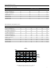
Specifications Frequency Coverage: Linear/Log Sweep: User-selectable linear or log sweep. In log sweep, step size logarithmically increases with frequency. Model/Option No. Frequency Coverage Output Type MG3691A 2 to 8.4 GHz K(f) MG3692A 2 to 20 GHz K(f) Number of Steps: Variable from 1 to 10,000 MG3693A 2 to 30 GHz K(f) Step Size: 0.01 Hz to the full frequency range of the instrument.
Sweep Triggering Sweep triggering is provided for Analog Frequency Sweep, Step Frequency Sweep, List Frequency Sweep, and CW Power Sweep. Auto: Triggers sweep automatically. External: Triggers a sweep on the low to high transition of an external TTL signal. AUX I/O connector, rear panel. Power: 85-264 Vac, 48-440 Hz, 250 VA maximum Standby: With ac line power connected, unit is placed in standby when front panel power switch is released from the OPERATE position.
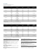
Spectral Purity All specifications apply at the lesser of +10 dBm output or maximum specified leveled output power, unless otherwise noted. Spurious Signals Power Line and Fan Rotation Spurious Emissions (dBc): Harmonic and Harmonic Related: Frequency Range Offset from Carrier Standard 0.1 Hz to 10 MHz (Option 22) <–30 dBc Frequency Range <300 Hz 300 Hz to 1 kHz >1 kHz 10 MHz to ≤100 MHz (Option 4) <–40 dBc ≥10 to ≤500 MHz (Option 4) >100 MHz to ≤2.
Single-Sideband Phase Noise Single-Sideband Phase Noise (dBc/Hz): Offset from Carrier Frequency Range 100 Hz 1 kHz 10 kHz 100 kHz ≥0.1 Hz to <10 MHz (Option 22) –90 –120 –130 –130 ≥10 MHz to <500 MHz (Option 4) –94 –106 –104 –120 ≥500 MHz to <2.
RF Output Power level specifications apply at 25 ±10˚C. Maximum Leveled Output Power**: Model Number Configuration Frequency Range (GHz) Output Power (dBm) Output Power With Step Attenuator (dBm) Output Power With Electronic Step Attenuator (dBm) MG3691A w/opt 4 w/opt 5 STD ≤2.2 GHz ≤2 GHz ≥2 to ≤8.4 GHz +17.0 +17.0 +13.0 +15.0 +15.0 +11.0 +13.0 +13.0 +9.0 MG3692A w/opt 4 w/opt 5 STD ≤2.2 GHz ≤2 GHz ≥2 to ≤20 GHz +17.0 +17.0 +13.0 +15.0 +15.0 +11.
Accuracy and Flatness Other Output Power Specifications Accuracy specifies the total worst case accuracy. Flatness is included within the accuracy specification. Output Units: Output units selectable as either dBm or mV. Selection of mV assumes 50Ω load. All data entry and display are in the selected units. Step Sweep and CW Modes: Attenuation Below Max Power Output Power Resolution: 0.01 dB or 0.
Modulation Frequency Generator Multiplication/Division Ratios: Frequency/Phase Modulation (Option 12) Divide Ratio, n Frequency Range Option 12 adds frequency and phase modulation, driven externally via a rear panel BNC connector, 50Ω. For internal modulation, add LF Generator Option 23. Frequency/Phase Modulation is not available <10 MHz with Option 22. <10 MHz (Option 22) modulation not available ≥10 to ≤15.625 MHz (Option 4) 256 >15.625 to ≤31.
Amplitude Modulation (Option 14) Frequency Range Rise & Fall Time (10% to 90%) Overshoot ≥10 to <31.25 MHz (Opt. 4) 400 ns* 33%* 40 ns* ±70 mV* ≥31.25 to <125 MHz (Opt. 4) 90 ns* 22%* 12 ns* ±130 mV* DC to 50 kHz minimum DC to 100 kHz typical ≥125 to <500 MHz (Opt. 4) 33 ns* 11%* 12 ns* ±70 mV* Flatness (DC to 10 kHz rates): ±0.3 dB ≥500 to <2200 MHz (Opt. 4) 15 ns 10% 12 ns* ±15 mV* ≥10 to <1000 MHz (Opt. 5) 15 ns 10 ns* 10% 8 ns* ±15 mV* ≥1 to <2 GHz (Opt.
IF Up-Conversion (Option 7) Option 7 adds an internal mixer that can be used for the generic up-conversion of an IF signal. The mixer’s RF, LO, and IF ports are made available at the rear panel of the MG3690A, via three female K-Connectors. The typical application will feed the MG3690A microwave output, which can be moved to the rear panel via option 9K, to the mixer’s LO port. An external IF signal will be fed to the mixer’s IF port. The new up-converted signal will be available at the mixer’s RF port.
mmW Frequency Coverage Millimeter Wave Multipliers (54000 Series plus Option 18) External multipliers can be added to the MG3690A to provide coverage as high as 110 GHz. Please call us for solutions beyond 110 GHz. The 54000 series multipliers provide 50 to 75 GHz coverage in WR15 or 75 to 110 GHz in WR10. An MG3690A with Option 18, mmW bias, is required to drive these multipliers. The MG3692A provides the input frequencies which are below 20 GHz.
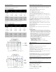
Inputs and Outputs Nomenclature EXT ALC IN * RF OUTPUT (Option 9) Input/Output Connectors Type** Location BNC Rear Panel K Connector (female) fmax ≤40 GHz Standard-Front Panel V Connector (female) fmax ≥40 GHz Option 9-Rear Panel 10 MHz REF IN BNC Rear Panel 10 MHz REF OUT BNC Rear Panel HORIZ OUT BNC Rear Panel Rear Panel EFC IN BNC AUX I/O 25 pin D-type Rear Panel SERIAL I/O RJ45 Rear Panel IEEE-488 GPIB Type 57 Rear Panel mmW/BIAS* (Option 18) Twinax Rear Panel RF, LO, I
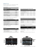
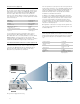
AUX I/O (Auxiliary Input/Output) Provides for most of the rear panel BNC connections through a single, 25-pin, D type connector. Supports master-slave operation with another synthesizer or allows for a singlecable interface with the Model 56100A Scalar Network Analyzer and other Anritsu instruments. (see figure below) EXT ALC IN Provides for leveling the RF output signal externally with either a detector or power meter. Signal requirements are shown in the RF Output specifications.
Ordering Information Models MG3691A 2 – 8.4 GHz Signal Generator MG3692A 2 – 20 GHz Signal Generator MG3693A 2 – 30 GHz Signal Generator MG3694A 2 – 40 GHz Signal Generator MG3695A 2 – 50 GHz Signal Generator MG3696A 2 – 65 GHz Signal Generator Options and Accessories 14 MG3690A/1A Rack Mount with slides – Rack mount kit containing a set of track slides (90 degree tilt capability), mounting ears, and front panel handles to let the instrument be mounted in a standard 19-inch equipment rack.
Millimeter Wave Accessories (Requires MG3690A Option 18) 54000-4WR15 50 to 75 GHz, V Band X4 Multiplier-Source Module (includes A36599 power cable and 3 filters). 54000-5WR15 50 to 75 GHz, V Band X4 Multiplier-Source Module with internal reference coupler/detector (includes A36599 power cable, 3 filters, and 560-10BX-2 detector adapter cable). 54000-4WR10 75-110 GHz, W Band X6 Multiplier-Source Module (includes A36599 power cable and 3 filters).
SALES CENTERS: United States (800) ANRITSU Canada (800) ANRITSU South America 55 (21) 2527-6922 Europe 44 (0) 1582-433433 Japan 81 (46) 223-1111 Asia-Pacific (65) 6282-2400 Microwave Measurement Division 490 Jarvis Drive, Morgan Hill, CA 95037-2809 http://www.us.anritsu.com ©Anritsu, October 2004. All trademarks are registered trademarks of their respective companies. Data subject to change without notice. 16 11410-00327 Rev.