ML2430A SERIES POWER METER OPERATION MANUAL ANRITSU LTD (EMD) RUTHERFORD CLOSE STEVENAGE HERTS SG1 2EF P/N: 10585-00001 REVISION: K PRINTED: MARCH.
WARRANTY The ANRITSU product(s) listed on the title page is (are) warranted against defects in materials and workmanship for one year from the date of shipment. ANRITSU's obligation covers repairing or replacing products which prove to be defective during the warranty period. Buyers shall prepay transportation charges for equipment returned to ANRITSU for warranty repairs. Obligation is limited to the original purchaser. ANRITSU is not liable for consequential damages.
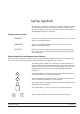
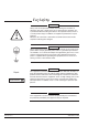
Safety Symbols To prevent the risk of personal injury or loss related to equipment malfunction, ANRITSU Company uses the following symbols to indicate safetyrelated information. For your own safety, please read this information carefully BEFORE operating the equipment. Symbols used in manuals DANGER Indicates a very dangerous procedure that could result in serious injury or death if not performed properly.
For Safety WARNING Always refer to the operation manual when working near locations at which the alert mark, shown on the left, is attached. If the operation, etc., is performed without heeding the advice in the operation manual, there is a risk of personal injury. In addition, the equipment performance may be reduced. Moreover, this alert mark is sometimes used with other marks and descriptions indicating other dangers.
Table of Contents Chapter 1 - General Information 1-1 Scope of This Manual . . . . . . . . . . . . . . . . . . . . . . . . . . 1-1 1-2 Introduction . . . . . . . . . . . . . . . . . . . . . . . . . . . . . . . . 1-1 1-3 Related Manuals . . . . . . . . . . . . . . . . . . . . . . . . . . . . . 1-1 1-4 Identification Number . . . . . . . . . . . . . . . . . . . . . . . . . . . 1-2 1-5 Power Meter Models, Options, and Accessories . . . . . . . . . . . . . 1-2 1-6 Sensors. . . . . . . . . . . . . . .
Chapter 5 - Procedures 5-1 Introduction . . . . . . . . . . . . . . . . . . . . . . . . . . . . . . . . 5-1 5-2 Power Measurement . . . . . . . . . . . . . . . . . . . . . . . . . . . 5-1 5-3 Zeroing the Sensor . . . . . . . . . . . . . . . . . . . . . . . . . . . . 5-1 5-4 Sensor Calibration . . . . . . . . . . . . . . . . . . . . . . . . . . . . 5-2 5-5 Sensor Zero/Cal . . . . . . . . . . . . . . . . . . . . . . . . . . . . . 5-3 5-6 Performance Verification . . . . . . . . . . . . . . . . . .
Appendix A - Specifications A-1 Introduction A-1 A-2 System Specifications . . . . . . . . . . . . . . . . . . . . . . . . . . A-1 A-3 System Defaults . . . . . . . . . . . . . . . . . . . . . . . . . . . . . A-6 A-4 System Error Messages . . . . . . . . . . . . . . . . . . . . . . . . A-11 Appendix B - GPIB Quick Reference B-1 Introduction B-1 B-2 ML24XXA Quick Reference . . . . . . . . . . . . . . . . . . . . . . . B-1 B-3 ML4803A Quick Reference . . . . . . . . . . . . . . . . . . . . . . .
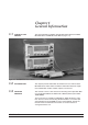
Chapter 1 General Information 1-1 SCOPE OF THIS MANUAL This manual provides installation and operation information for the Model ML2430A Series of ANRITSU Power Meters (Figure 1-1). Figure 1-1. ML2430A Series Power Meters 1-2 1-3 INTRODUCTION This chapter provides information to familiarize the user with the basic ML2430A Series Power Meter. Included is information about the equipment identification number, models, options, and sensors.
IDENTIFICATION NUMBER 1-4 1-5 GENERAL INFORMATION IDENTIFICATION NUMBER The ML2430A Series ID number is affixed to the rear panel (see Figure 3-2). Please use the complete ID number when ordering parts or corresponding with the Anritsu Customer Service department. POWER METER MODELS, OPTIONS, AND ACCESSORIES The ML2430A Series Power Meter is available with either one or two sensor inputs, and is delivered with a 1.5m sensor cable (ML2400A-20) for each input.
GENERAL INFORMATION 1-6 SENSORS SENSORS The following sensors, sensor options, and sensor accessories are available for use with the ML2430A Series Power Meters: Power Sensors (–70 to + 20 dBm) Range Model No. MA2468A 10 MHz – 6 GHz MA2469B 10 MHz – 18 GHz (–60 to +20 dBm, nominal bw 1.2 MHz) MA2472A 10 MHz – 18 GHz MA2473A 10 MHz – 32 GHz MA2474A 10 MHz – 40 GHz MA2475A 10 MHz – 50 GHz Thermal Sensors (–30 to + 20 dBm) Range Model No.
SENSORS NOTE The use of sensor cables greater than 10 meters in length is not recommended when measuring pulses of less than 10 ms. 1-4 GENERAL INFORMATION Sensor Accessories ML2400A-20 ML2400A-21 ML2400A-22 ML2400A-23 1.5m Sensor Cable 0.
Chapter 2 Installation 2-1 2-2 INTRODUCTION This chapter provides information for the initial inspection and preparation for use of the ML2430A Series Power Meter. Shipping and storage information is also included. INITIAL INSPECTION Inspect the shipping container for damage. If the container or cushioning material is damaged, retain until the contents of the shipment have been checked against the packing list and the instrument has been checked for mechanical and electrical operation.
POWER REQUIREMENTS INSTALLATION a fuse mounted inside the unit, on the main board. A grounding terminal is provided on the rear panel to ground the unit during operation from a DC supply. Battery Power The ML2430A Series Power Meter can be operated using the optional internal battery pack. During battery operation, an icon will be displayed on measurement screens indicating the state of charge.
INSTALLATION 2-5 ENVIRONMENTAL REQUIREMENTS ENVIRONMENTAL REQUIREMENTS Fuses The ML2430A Series Power Meter AC and DC input lines are protected by internally mounted fuses. These fuses should only be changed by qualified service personnel. Replace only with fuses of the same type and rating (AC fuse is 2A, 250V, slow-blow; DC fuse is 3A, 125V, slow-blow). Grounding The ML2430A Series Power Meter must be properly grounded. Failure to ground the instrument could be hazardous to operating personnel.
RACK MOUNTING INSTALLATION The required parts and tools are listed below: Quantity (each) Description Anritsu Part Number 2 HANDLE, PULL, CHASSIS, PLASTIC, HARDWARE 783-1055 4 SPEED NUT 790-319 8 6-32, SST, WASHER, FLAT 900-345 4 M4, 8.
INSTALLATION RACK MOUNTING Locate the support bracket on the four PM case pillars. Secure with 4 screws 905-68 and 4 washers 900-345. (See max. torque settings page 2-4.) 5. Locate the front rack mounting bracket C37276 at the front of the PM on the other side to the large support bracket with two screws 905-68 and two washers 900-345. (See max. torque settings page 2-4). 6.
RACK MOUNTING INSTALLATION ML2400A-03 Rack Mount Installation This section describes the assembly procedure for fitting two ML2430A Power Meters (PM) into a instrument rack. The PM’s must be fitted with rack mount top and bottom covers for the rack mount kit to be fitted. The procedure involves fitting support brackets, two front handles, and two rear support brackets, one to each PM. The two PM,s which are locked together can then be loaded and secured in the rack position desired.
INSTALLATION RACK MOUNTING Tools Required: Assembly Procedure 1 Small Phillips screw driver 1 Large Phillips screw driver 1 Small Phillips torque screw driver 10cNm to 120cNm. 1 Assembly drawing “ML2400/03 SIDE BY SIDE OPTION” 1. Confirm the correct tools are available and the parts listed above are present. Refer to diagram on page 2-8 throughout this procedure. 2.
RACK MOUNTING INSTALLATION 49415 RACKMOUNT SIDE BRACKET (MULTI-FIT).
BATTERY CHARGING, REMOVAL AND REPLACEMENT 2-7 BATTERY CHARGING, REMOVAL AND REPLACEMENT INSTALLATION The optional ML2430A Series Power Meter battery is a 12 Volt, 3000 mA-h nickel-metal hydride (Ni-MH) multi-cell pack, located in a compartment on the bottom of the housing. The compartment cover is secured by fractional turn fasteners, as shown in Figure 2-1. Rotate the fasteners approximately ¼-turn counterclockwise to release the cover.
INSTALLATION BATTERY CHARGING, REMOVAL AND REPLACEMENT CAUTION • To avoid excessive heat build up, always remove the ML2430A from the optional soft sided carrying case (D41310) before selecting fast charging. For optimal battery life, the battery should be fully discharged before recharging. Repeated partial charge/discharge cycles can result in a loss of battery capacity, recoverable by applying several “conditioning” (full charge/discharge) cycles.
INSTALLATION 2-8 STORAGE AND SHIPMENT STORAGE AND SHIPMENT The following paragraphs describe preparing the power meter for storage and shipment. Preparation for Storage Preparing the power meter for storage consists of cleaning the unit and packing it with moisture-absorbing desiccant crystals. Whenever the unit is to be stored for an extended period (longer than one week), it is advisable to remove the optional battery pack.
STORAGE AND SHIPMENT INSTALLATION Table 2-3. ANRITSU Service Centers UNITED STATES FRANCE KOREA ANRITSU SALES COMPANY 685 Jarvis Drive Morgan Hill, CA 95037-2809 Telephone: (408) 776-8300 FAX: (408) 776-1744 ANRITSU S.
Chapter 3 Connections 3-1 3-2 INTRODUCTION This chapter describes physical connections to the power meter on both the front and rear panels. FRONT PANEL CONNECTORS The front panel connectors are illustrated in Figure 3-1. Detailed descriptions of each connector follow. Calibrator Connector Sensor A Connector Sensor B Connector (ML2438A only) Figure 3-1. Model ML2430A Series Power Meter Front Panel Connectors Calibrator 0.
REAR PANEL CONNECTORS CONNECTIONS An optional rear panel Calibrator connector is offered as an alternative (see Figure 3-2). If the rear panel connector option is installed, the front panel connector is not installed. Refer to Chapter 5, Procedures, for information on using the Calibrator output. Sensor A Connector This connector is a 12-pin circular precision connector to be used in conjunction with power sensor cables.
OPERATION REAR PANEL CONNECTORS ID Number Label Parallel Printer Port GPIB/ IEEE488 Connector Standard General Purpose Interface Bus connector used to connect through GPIB to other test equipment and a host computer. The ML2430A Series is compatible with IEEE-488.1 requirements. Refer to Chapter 6, GPIB Programming for information on using GPIB. Provides an interface to a standard parallel printer.
Chapter 4 Front Panel Operation 4-1 4-2 INTRODUCTION The ML2430A Series Power Meter is controlled from the front panel using the five main menu keys; Sensor, Channel, Trigger, System, and Cal/Zero. This chapter explains the power-on procedure and the features and functions of each of the menus. Also refer to Appendix C for quick reference Menu Maps. FRONT PANEL CONTROLS The front panel controls are shown and described in Figure 4-1.
FRONT PANEL CONTROLS OPERATION Graphic LCD with Backlight Soft Keys The LCD display settings are configured in the System menus. The backlight can be turned on or off, or time delayed, as required to suit ambient conditions and battery drain. The backlight is controlled through the System menus when operating from the internal battery. Soft keys select submenus, toggle selections, control cursor position, and allow data entry.
OPERATION 4-3 POWER-ON PROCEDURE POWER-ON PROCEDURE At power-on, the power meter performs a brief power-on self test (POST). After the POST, the instrument loads the last used configuration and display settings. If a POST error occurs, information and available options will be displayed on the screen.
POWER-ON PROCEDURE OPERATION If any error, other than a DSP error, is encountered, the text: “Press ANY key to continue” will be displayed at the bottom of the screen. If only warnings are encountered, nothing will be displayed at the bottom of the screen, and the unit will continue to initialize. If a DSP error occurs, the text: "Restart unit. If error persists, con-tact Service Center." is displayed and the unit will halt the self test.
OPERATION 4-4 SENSOR MENU SENSOR MENU The Sensor menu has controls for sensor data processing. NOTE When editing an entry in a menu, pressing the CLR key clears the digits. If in a menu screen, pressing the CLR key returns to the previous menu level. Setup NOTE The MODE selection is not available in Profile or Source Sweep modes. NOTE When measuring modulated signals with a diode sensor, ensure Modulated Average is selected or measurement errors may result.
SENSOR MENU OPERATION NOTE The HOLD selection is not available when System/Setup/mode is set to Source Sweep. In this mode, AUTO ranging is used. NOTE HOLD [RGH] Typical Range Hold values for diode sensors are: SETTLE % [SENSTL] SETTLE% affects GPIB speed. Consider this when optimizing GPIB performance. Calfactor Allows the operating range of the selected sensor to be set to the desired range. Select a Range Hold value of 1 to 5, or Auto.
OPERATION SENSOR MENU For greater accuracy, calibration factors are interpolated for settings that are between the calibration factor data provided in the sensor EEPROM. For example, if calibration factors exist for 1 and 2 GHz, then the calibration factor applied for 1.5 GHz will be a value midway between the two. NOTE When the MA2499B Anritsu Sensor Adapter or the MA2497A HP Sensor Adapter are used, the input frequency should be set to 50 MHz irrespective of the measurement frequency.
SENSOR MENU OPERATION Factory Selects the Factory calibration factor table. Pressing Factory and the +/- key on the numeric keypad allows selection of a userdefined table in addition to the factory table. This allows full factory calibration to be active, and allows adjustments or corrections to be entered in the user-defined table.
OPERATION SENSOR MENU SETUP [CVSTF CVSPF CVSTV CVSPV] Averaging Sets up the Start and Stop frequencies and voltages when Source is set to V/GHz. This tells the ML2430A how to determine the frequency of the swept signal based on the applied rear panel voltage. Sensor data averaging. The available soft keys depend upon the operating mode selected. In Readout and Power vs. Time modes, the following soft keys appear: SENSOR Model ML2438A (dual channel) only. Select sensor A or B, in Power vs.
SENSOR MENU OPERATION REPEAT averaging also allows the user to manually select the amount of averaging regardless of the signal level, however the display is updated only when the NUMBER of readings specified have been taken (1-512). NOTE GPIB trigger commands automatically apply REPEAT averaging after TR2 commands to ensure ‘old’ samples are excluded from the measurement. However, the user should be aware that due to the high speed of the meter, other instruments in the ATE system may not be settled.
OPERATION SENSOR MENU RESET Sweep average reset. If the graph sweep averaging state is ON, this key resets the data points and restarts the sweep to sweep mode. CURSOR [GRSWR] Offset Between cursor averaging ON or OFF. When ON, a digital readout of the average power between the two cursors is displayed in the readout area of the PROFILE display. Allows an offset, in dB, to be applied to sensor data for the selected sensor. SENSOR Model ML2438A (dual channel) only.
SENSOR MENU OPERATION TABLE [OFFTBL OFFTBR OFFTBU OFFVAL] Select the offset table number (1-5) when Offset TYPE is set to Table. When a table is selected, additional soft keys become available: EDIT This will bring up all of the selected offset table’s entries, with their associated frequencies and offsets. Select an entry and enter the frequency and offset using the keypad. CLEAR [OFFCLR] When an offset table is selected, CLEAR will set all of the table’s elements to zero.
OPERATION 4-5 CHANNEL MENU CHANNEL MENU The Channel menu controls the operation of a display channel. There are two display channels, Channel 1 and Channel 2. Channel 1 appears at the top of the readout display and channel 2 at the bottom. If a channel input configuration is turned off, the remaining channel appears in the center of the screen. NOTE When editing an entry in a menu, pressing the CLR key clears the digits. If in a menu screen, pressing the CLR key returns to the previous menu level.
CHANNEL MENU OPERATION RESET [MMRST] Rel 1 [REL] This function resets the Min/Max (when ON) for the channel selected. After the relative power level is set by the operator, the Relative mode subtracts that value from the current measured power. If selected when in Relative mode, the relative operation for channel one is turned off. Pressing the Rel 1 soft key when in Readout mode will subtract the last used relative value. Hold down the key to retake this value. The readout will display 0.00 dBr.
OPERATION CHANNEL MENU have been set for –10 dBm and the display units are subsequently changed from dBm to Watts, the system still checks for the reading to rise above –10, even though the display units type has been changed. Enter a value from: NOTE In Profile mode, the limit value is only checked against dB values as Profile mode only works in dB. Units Min Max dBm –99.99 +99.99 dBmV –53.00 147.00 dBµV 7.00 207.00 Watts 0.0 50.
TRIGGER MENU 4-6 TRIGGER MENU OPERATION The Trigger function in the ML2430A allows the user to define under what conditions measurements are taken, and the time period they are taken over. For instance, the READOUT mode can be configured to display the average power of the ON period of a square wave, or an individual slot in a GSM burst. The Trigger menus are always available in PROFILE operation mode, as selected from the System menu.
OPERATION TRIGGER MENU The trigger icons appear as shown in Figure 4-2. Modulated Average MOD Continuous Manual Rising Edge Falling Edge Internal A INT A INT A Internal B INT B INT B TTL TTL NOTE External trigger is only effective at 800 KHz or lower. MAN External Figure 4-2. Trigger Icons Only when a channel input configuration includes a sensor with a measurement mode that requires an icon, will an icon be displayed.
TRIGGER MENU OPERATION DELAY [TRGDLY GTDLY] In Profile mode, DELAY sets the time delay (after the display trigger delay) to when the system starts to take and display readings, represented by the left most cursor. Enter 0.0 to 1.0 seconds, in ms or ms. NOTE Changing the left most cursor, or the trigger delay time, updates the cursor or the delay time value accordingly. In Profile mode, moving the cursor only allows updates to the pixel resolution of the display. In Power vs.
OPERATION TRIGGER MENU -9 GSM BURST FROM GENERATOR dBm -50 BURST TRIGGER SYNC FROM GENERATOR TTL Figure 4-3. Typical Arming Diagram 1. Connect to the rear panel digital input. 2. Select Trigger|Setup|ARMING|Blanking ON. 3. Set the polarity of the blanking (System menu) Example power meter reading: –9.16 dBm. NOTE Effective range is to approximately –30 dBm and is only active in DC ranges 1 and 2.
TRIGGER MENU OPERATION Figure 4-4 shows a typical trigger timing diagram. Note that the display trigger delay is only present when in Profile operation mode, and helps in setting the ‘window’ position along the signal. PRETRIGGER % CURSOR 1 CURSOR 2 GATE WIDTH DELAY INCOMING SIGNAL FROM SENSOR DISPLAY TRIGGER DELAY (PROFILE MODE) DATA COLLECTION TIME (PROFILE MODE) TRIGGER POINT Figure 4-4.
OPERATION 4-7 SYSTEM MENU SYSTEM MENU The System menus control the operating modes, display visibility, sound, rear panel functions, and battery state of the ML2430A Series Power Meter. Note that the soft keys will appear differently depending upon the operation mode selected with the Setup soft key below. NOTE When editing an entry in a menu, pressing the CLR key clears the digits. If in a menu screen, pressing the CLR key returns to the previous menu level.
SYSTEM MENU OPERATION With LINK readout/profile trigger set to ON, switching to Readout mode uses the same trigger conditions, but allows the full dynamic range of the meter to be used, as well as providing full GPIB speed on data acquisition. NOTE With LINK set to ON, Readout mode is temporarily forced to Custom mode, and the default and Mod Average modes are inhibited. To use these modes, deselect LINK.
OPERATION NOTE SYSTEM MENU DATA HOLD [GRPIX] This selects how the graph is displayed on the screen. Select from NORMAL, Min&Max, Min, or Max. NOTE If either Min&Max, Min, or Max is selected, the display will keep the “old” data and may appear stationary. The DATA HOLD mode in use is displayed on the left of the screen, below the middle value of the y axis. Useful for tracking peak levels over a period of time, or detecting glitches.
SYSTEM MENU OPERATION Anritsu 68/69000 Synthesized Sweep Generator HORIZ OUT 10 MHz REF IN NOTE: USE SLOW BLO FUSES ONLY 10 MHz REF OUT ! HORIZ OUT HEAVY WEIGHT SEQ SYNC OUT LINE SELECT ! ML2430A Series Power Meter CAUTION DIGITAL INPUT 1 DO NOT OPERATE WITH POWER CORD UNGROUNDED EXT ALC IN INPUT 90 - 132VAC 180 - 264VAC 48 - 440Hz DWELL IN V/GHz OUT 110 220V 2.5A 110V 5A 220 AUX I/O CAUTION > 18 kg ANALOG INPUT 2 IEEE-488 GPIB SERIAL I/O SEQ SYNC OUT BNC Cables Figure 4-5.
OPERATION SYSTEM MENU STOP Sweep stop frequency (MHz or GHz) or power (dBm) [SRCSPFRQ SRCSPPWR] NOTE When the power meter is communicating with a signal source/generator over the serial interface, if the source frequency power level or the frequency itself is changed, the source sweep display will be updated where appropriate. Control The Control menu adjusts cursor position and toggles the readout display in Profile, Power vs. Time and Source Sweep modes, and provides control over display scaling.
SYSTEM MENU OPERATION 1 cursor 1 reading 2 cursor 2 reading DP Power difference between cursor 1 and cursor 2 Dt Time difference between cursor 1 and cursor 2 AV Between cursor average if ON Data hold = MIN (or MAX) : 1 cursor 1 minimum reading, or maximum if MAX mode 2 cursor 2 minimum reading, or maximum if MAX mode DP Power diff between cursor 1 and cursor 2 minimums (or maximums if MAX mode) Dt Time difference between cursor 1 and cursor 2 minimums (or maximums if MAX mode) Data hold
OPERATION SYSTEM MENU 2 cursor 2 reading DP Power difference between cursor 1 and cursor 2 X1 X axis at cursor 1 X2 X axis at cursor 2 Data hold = MIN (or MAX) : 1 cursor 1 minimum reading, or maximum if MAX mode 2 cursor 2 minimum reading, or maximum if MAX mode DP Power diff between cursor 1 and cursor 2 minimums (or maximums if MAX mode) X1 X axis at cursor 1 X2 X axis at cursor 2 Data hold = MIN&MAX: Display cursor 1 MIN reading cursor 1 MAX reading 2 cursor 2 MIN reading cursor
SYSTEM MENU Sound 4-28 OPERATION Contrast DOWN [DCONTD DCONT] Reduces the display contrast. Adjust to suit ambient conditions. Contrast UP [DCONTU DCONT] Increases the display contrast. Adjust to suit ambient conditions. TIMED [DBLTIM] Sets the time limit when the backlight will turn off if the BACKLIGHT setting is set to TIMED. Enter a value from 0.0 to 100.0 minutes. PEAKMETER [DPEAK] Turns on the peakmeter display for Sensor A, Sensor B, or both Sensors A and B.
OPERATION Print [PRINT] SYSTEM MENU This selection prints the screen and various operational settings through the rear panel printer port. ANRITSU Power Meter ML2437A s/n: 97180010 Firmware: 2.
SYSTEM MENU OPERATION NOTE Immediately after power-on, the “estimated operating time remaining” displayed may not be genuine, as the battery requires a few minutes to calculate the present rate of discharge. An accurate indication will be displayed only after a few minutes of continuous operation. CHARGE Rear Panel Available only when the instrument is being powered by AC line power or external DC power greater than 21 volts. This selection starts the battery charging cycle.
OPERATION NOTE For the power meter to communicate with Anritsu 68/69000-series synthesizers using Source IF, the synthesizer firmware must be later than the levels shown for the various models below: SYSTEM MENU Source IF allows the power meter to communicate with an Anritsu 68/69000-series synthesizer when the operation mode is set to Source Sweep. BAUD [RSBAUD] Sets the serial port BAUD rate. Select from 1200, 2400, 4800, 9600 (default), 19200, or 38400.
SYSTEM MENU OPERATION POWER [MODPWR] – If this is set, and the power cycles on the meter, then the number specified in the “phone number” field will be dialed. When a connection is established, an SRQ will be sent to the host PC. Remote communications can then continue as normal. BNC Configures the input and output rear panel BNC connectors. [OBMD, OBCH, OBVST, OBVSP, OBDST, OBDSP, OBCH, OBPL, OBACM, OBCH, OBZL, IBBLP] PORT Output 1 or 2: Select the output port to configure (see MODE below).
OPERATION SYSTEM MENU ACMod output (port 1 only) is a TTL signal synchronized to the internal chopper (when used) of the signal channel. This signal can be used for synchronization with external sources or when viewing AC range (chopped) signals. Leveling outputs - To allow the power meter to be used in a leveling loop, the signal channel output is available on the rear panel. The leveling loop will be broken every time the signal channel autoranges.
CAL/ZERO MENU Graphics NOTE These options allow either the min/max of each sweep to be displayed (single) or the conventional method for tracking variation of levels over an extended period of time (infinite). Secure [SECURE] Identity [*IDN, OI] 4-8 CAL/ZERO MENU This menu presents additional graphic display controls: CONNECT [GRCP] This control is normally ON and causes the data between samples to be interpolated and lines drawn between sample points.
OPERATION RF ON/OFF [RFCAL] Ext V [VZERO] CAL/ZERO MENU Turns the RF calibrator ON or OFF. Zeros the rear panel multi-purpose BNC connector used for Volts per GHz connection (Analog Input). This will calibrate the units to read zero volts on this BNC. During this operation the connector should either not be connected to anything, or should be connected to a 0 Volt source.
Chapter 5 Procedures 5-1 5-2 INTRODUCTION This chapter presents some common procedures for use with the ML2430A Series Power Meter. These procedures refer to the ML2430A Series front and rear panel connectors and front panel keys and menus as explained in Chapter 3, Connections, and Chapter 4, Front Panel Operation. The operator should be familiar with the front and rear panel layouts and with the use of the keys and menus before attempting these procedures.
SENSOR CALIBRATION PROCEDURES To zero the sensor without calibration, press the Cal/Zero front panel key and the Zero soft key, then select the appropriate sensor. ML2430A Cal/Zero Zero Sensor A Sensor B Figure 5-1. Sensor Zeroing Key Sequence Note that if only one sensor is connected, the A-B selection is not displayed and the zeroing process begins immediately. The message changes to SENSOR x ZERO . . . . On successful completion of the zeroing operation, the buzzer sounds.
PROCEDURES SENSOR ZERO/CAL Any error conditions encountered during calibration, for example the presence of extraneous noise or RF signals, will result in an error message on the front panel display. The sensors can also be calibrated using the GPIB CAL command (see Chapter 6, GPIB Operation). 5-5 SENSOR ZERO/CAL Sensors must be zeroed before being calibrated. The Zero/Cal function completes both operations in sequence.
PRINTER CONNECTION 5-7 PRINTER CONNECTION PROCEDURES See Chapter 3, Connectors, for the location of the parallel port connector on the rear panel. Connect a parallel printer cable from the ML2430A Series rear panel 25-pin D-sub connector to the printer. Select System|Print to begin printing. See Chapter 4, Front Panel Operation, for specific printer connector configuration options. Printing can also be initiated in ML24XXA (native) mode using the GPIB PRINT command (page 6-65).
PROCEDURES 5-9 SERIAL REMOTE OPERATION NOTE Serial interface remote operation is not available when the ML2430A Series Power Meter is operating from the internal battery. SERIAL REMOTE OPERATION The ML2430A Series Power Meter can be operated remotely through the rear panel serial connector (See Chapter 3, Connectors, for the location of the serial connector). Whereas GPIB has restrictions on total cable length and cable length between instruments, RS232 serial communication is not as limited.
RS232 MODEM SUPPORT PROCEDURES Requested data is returned in the same format as with GPIB, but with a preceding 'R' and a terminating new line character. SRQs are available, and are output as SRQ message 'S' followed by a terminating new line character. When the SRQ message has been received, an "!SPL" command (equivalent to the GPIB serial poll) can be issued. The power meter will respond with the serial poll data message which is a single character preceded by 'P' and terminated by a new line character.
PROCEDURES RS232 MODEM SUPPORT Connected Device GPIB/RS232 Modem Commands Character Sequence Computer connected directly "+++at\r\rS\n" Modem offline from phone network Sequence will be seen if remote connection established modem status data followed by "S\n" Modem connected through to remote computer "+++S\n" The following table lists the GPIB/RS232 Modem Commands and the special serial interface only commands: Command Parameter Definition !BYE RS232-type command only, allows the remote PC t
RS232 MODEM SUPPORT Modem Compatibility and Commands PROCEDURES The ML2430A Series Power Meter firmware supports Hayes-compatible modems.
PROCEDURES RS232 MODEM SUPPORT 4. To set a limit for channel 1 and to have the power meter autodial a remote computer when this limit fails, send the following sequence: LLIM 1,-12DBM LLIMS 1,ON MODLIM ON MODPH MODRED 3 MODDEL 2 Sets low limit on channel 1 to -12dBm Turn low limit testing ON for channel 1 Set meter to autodial when any limits fail Set phone number to be auto-dialed Set redial count to 3 Set delay between each attempt to dial to 2 min. 5.
PROFILE OPERATION MODE PROCEDURES a. Read the status register using the equivalent of a GPIB serial poll. Send the message: !SPL Note: There is NO terminator to this message. The power meter will respond: Px\n x is the ASCII character determined by the value in the meter status register. x = “B” gives a status register value of 01000010 binary. Comparing this with the status byte description in Section 6-7 of the manual will show that the SRQ and limits error bits are both set. b.
PROCEDURES NOTE To operate the Universal power sensors in profile mode Option 1 must be fitted. Activate option 1 mode before selecting profile mode under the SENSOR | Setup OPTION FAST CW menu. NOTE Dynamic range is limited in Profile mode to DC ranges only. For maximum dynamic range, measured signals need to be repetitive (not single-shot) when profiling over less than 30ms width. Above this, single-shot profiles can be measured over the full dynamic range.
PROFILE OPERATION MODE PROCEDURES NOTE With a CONTINUOUS trigger such as this, there will most likely not be specific points of interest, so the movement of the cursors is rather arbitrary. If modulation is applied to the signal, or its power level altered, the signal should change on the display. The signal may not be visible if it is not in the default range which covers +20 to –50 dBm.
PROCEDURES PROFILE OPERATION MODE cussed more fully in the Triggered Measurements section below. Range Hold may be selected (see page 4-6) to limit dynamic range and prevent small range change disturbances on very high speed signals. Use Range Hold 1 for measurements down to –25 dBm, and Range Hold 2 up to –25. If the display update is turned off via GPIB, only the average is updated.
PROFILE OPERATION MODE PROCEDURES The unique method of range changing applied in this mode means that the change between range 1 and 2 is effected in less than 2 ms. In most cases it is not noticeable, although there may be a slight discontinuity. Due to the range-change method, if a triggered signal is not repetitive the range change may not settle instantly, and the displayed result may be in error.
PROCEDURES PROFILE OPERATION MODE NOTE For smaller values of display trigger delay, it is possible that the display will cover time intervals (on the left of the display) for which there is no data. In these conditions, the cursors are normally prevented from displaying data taken there as it will be in error (there is no data). The position of ‘x’ is nominally 10% of the screen.
SOURCE SWEEP MODE PROCEDURES (a) CONNECT points. With this ON (default) the data points are connected with vectors to resemble a real time trace. When OFF, the data points are displayed as data points only, with no connecting line. This can give a faster display update, however, it may be confusing as near vertical lines will have very few points defined within them.
PROCEDURES Frequency Sweep Mode SOURCE SWEEP MODE When the sensor/cal factor source is set to V/GHz in Source Sweep mode, the start and stop voltages are assumed to be 0 and 10V, and the start and stop frequencies are taken from the System|Source sweep menu. Calibrate the V/GHz setup by setting 0 and 10v and the frequencies (F1 and F2) that these voltages correspond to (sweep width).
POWER vs. TIME MODE PROCEDURES System|Source Sweep|Data Hold can be used to select the way in which data is plotted. Using Min/Max variation (both minimum and maximum) can be shown on the display. Using Max effectively provides a peak hold. If the display of swept power is not what is expected, check the setting of AVERAGE and the DATA HOLD mode in case it is affecting the data processing.
PROCEDURES USER CAL FACTORS The data can be displayed as a maximum value only, a minimum value only, maximum and minimum values, the average of all the readings during the time slot period, or the latest measured value. These display modes are selected in the SYSTEM|PwrVsTime menu, DATA HOLD representation. Measurement setup, i.e., trigger, etc., is selected the same way as in Readout mode. The minimum sweep time is 1 minute, and the maximum sweep time is 24 hours.
USER CAL FACTORS PROCEDURES Cal factor tables are accessed through the Sensor|CalFactor|USE TABLE front panel menus (Chapter 4), or through GPIB commands (Chapter 6). ML2430A Sensor CalFactor -moreUSE TABLE %/dB EDIT Figure 5-4. Cal Factor Table Key Sequence Example Procedure Use the key sequence Sensor|Cal Factor|EDIT to get to the table edit menu. Use the TABLE key to select the table, then the EDIT key to edit that table. Press the INSERT key to enter frequency and cal factor data pairs.
PROCEDURES 5-15 OPTIMIZING READINGS OPTIMIZING READINGS This section presents information on how to get the fastest readings from the ML2430A Series power meter when operating under GPIB control. Refer to Chapter 6, GPIB Operation, for specific command descriptions. Measurement speed depends greatly on the type of measurements being taken, the power level, and the amount of settling used. NOTES All results shown in this section are from DOS programs running on a 200 MHz controller using IEEE 488.
OPTIMIZING READINGS PROCEDURES Send(0, 13, “O 1”, 3L, NLend); Receive(0, 13, buffer[i], 20, STOPend); } Settling (%) Power Level (dBm) Readings/Second 0.1 0 160 0.1 –30 160 10.0 –30 160 The 0.1% settling on –30 dBm power level results were not improved because of the amount of time needed to settle to 0.1% on –30 dBm. FAST ON/OFF command Using the FAST command (page 6-37) limits the types of measurements that can be taken.
PROCEDURES Using Buffered Requests OPTIMIZING READINGS Using the buffered Output channel ON command (page 6-64), even faster measurement speeds can be achieved. By using the ON command instead of the O command x number of times, extra processing is removed, resulting in improved speed. NOTE Using FAST mode here will not increase the speed as this mode only works when asking for one measurement at a time (i.e., the ‘O’ command only.
OPERATOR MAINTENANCE PROCEDURES AN EXAMPLE PROGRAM IN C #include /* include the NI 488.2 GPIB include file */ #include “DECL.H” /* LINK with MCIB.LIB */ /* Compiled with BorlandC++ 2.
Chapter 6 GPIB Operation 6-1 6-2 INTRODUCTION This chapter provides alphabetically-ordered listings and descriptions of all ML2430A Series GPIB programming commands. The majority of the GPIB commands have equivalents in the front panel menu settings. Note that GPIB operation is not available when the power meter is running from the internal battery (option ML2400A-11). The ML2430A Series Power Meter supports the IEEE 488.
DATA I/O FORMATS GPIB OPERATION HP and ML4803 emulation commands on the other hand, do not have to have a space between the command header and the parameter, or commas between the parameters. The format for HP emulation commands is: ... The end of the command text must be terminated with either a line feed character (0Ah, decimal 10) or a GPIB End of Transmission State (EOI), or both.
GPIB OPERATION DATA I/O FORMATS All of the Status enable type commands (*SRE for example) Stored numbers (i.e., 0, 1, 2, 3, 4, 5) Offset table numbers (i.e., 1, 2, 3, 4, 5, 6...) GPIB addresses (1 to 30) User Averaging number in the AVG command (1 to 512) Display contrast number (1 to 12). The ML2430A Series data formats are summarized below: This notation represents ASCII integer values. A comma (,) is used to separate multiple values sent in a single command input or output string.
QUERY COMMANDS GPIB OPERATION “1/15/98" ”Save “”cal_file"" now." 'Save “cal_file” now.' 6-4 This notation represents undelimited 7-bit ASCII text. The end of the text must be terminated with the line feed character (0Ah, decimal 10) or a GPIB End of Transmission State (EOI), or both. This requirement makes it necessary for text to be transmitted only at the end of a program or response message, that is, at the end of a multiple input or output statement.
GPIB OPERATION 6-5 GPIB PC CARD SETUP GPIB PC CARD SETUP The following GPIB driver configuration set up is recommended for reliable GPIB communication with the ML2430A Series power meter. The set up is expressed in the terms used by the National Instruments GPIB ISA and PCI cards and drivers for WIN95 and DOS. GPIB Device Template The ML2430A Series default primary address is 13. Separate device templates for the primary address of each device can usually be set up separately.
USING 488.1 GPIB 6-6 USING 488.1 GPIB GPIB OPERATION IEEE 488.1 level commands are in the form of data byte codes with the attention (ATN) line set. A separate function is normally provided to drive these commands from a GPIB program. A typical GPIB driver library call for 488.1 and 488.2 is given for each of the following commands. Refer to the IEEE 488.1 and IEEE488.2 device driver manuals for full definitions of the responses, and to find the actual command format for your GPIB driver library.
GPIB OPERATION USING 488.2 GPIB Typical device library calls are 488.1 'ibrsp' and 488.2 'ReadStatusByte'. 6-7 USING 488.2 GPIB 488.2 Command Format The IEEE 488.1 GPIB standard was updated in 1987 to 488.2 to better enforce standardization of GPIB communication. This section explains the fundamentals of 488.2 GPIB operation and how it is implemented in the ML2430A Series Power Meter. Refer to the full IEEE 488.2 standard for more detailed information.
USING 488.2 GPIB GPIB OPERATION OPC Operation Complete. When a program message that includes the *OPC command has been completed, and the GPIB interface is idle, with any responses read out of the output buffer this bit is set. For example, if the last command in a configuration sequence is *OPC, the OPC bit in the event status register will be set when that configuration list has been completed. Also refer to Figure 6-2, page 6-13, IEEE 488.2 Standard Status Structures.
GPIB OPERATION SERVICE REQUEST STATUS (SRQ) 2. Request data from display channel 1 by sending: O 1 The SRQ will be set with the new reading which will now be in the output buffer ready to be read. The data should now be read so that the MAV bit will be cleared. If the data is not read, or the output buffer not cleared, and another request for data is made this data will be buffered after the previous data. Getting a Reading The 488.
FUNCTIONAL GROUPS ESB 6-9 FUNCTIONAL GROUPS GPIB OPERATION If any of the event register bits are set and the corresponding event status enable bits are set the ESB bit in the status byte will be set. This bit can be used to set an SRQ by setting the same bit in the SRE register using the *SRE command. The ESB bit is cleared when the ESR is read by using the *ESR? command (pages 6-14, 6-54, 6-101).
GPIB OPERATION GROUPS FUNCTIONAL SENSOR The SENSOR group commands select the data acquisition controls for the selected sensor. SYSTEM The SYSTEM group commands control the overall functionality of the ML2430A Series Power Meter, including the system operation mode, cursor control, display configuration, sound, printing, battery control and status, rear panel configuration, graphics, system security, and system identity.
ML24XXA NATIVE COMMANDS 6-10 ML24XXA NATIVE COMMANDS GPIB OPERATION This section provides an alphabetical listing of the GPIB commands (mnemonics) used to program the Model ML2430A Series Power Meter in ML24XXA (native) mode. The emulation mode can be set through the front panel SYSTEM|more|more|Rear panel|GPIB|MODE menu (see Chapter 4, Operation) or through the GPIB command EMUL (page 6-35).
GPIB OPERATION ML24XXA NATIVE COMMANDS configuration combines sensors, the combination is done in linear units. If the result of the combination produces a negative linear value and the displayed units are log (i.e., dB) this would be an illegal logarithmic operation. Printer error - A print was requested and this error was returned. Request for data from a channel with no sensor connected. Bit 0: Operation Complete.
ML24XXA NATIVE COMMANDS *ESE? Return Event status register enable mask Syntax: Remarks: *ESR? Remarks: Remarks: *OPC Returned format: When converted to an 8-bit binary number, this byte yields the bit settings of the register. Return the value of the standard event status register. Afterwards the event status register are cleared. The returned format is: . When converted to a 8-bit binary number, this byte yields the bit settings of the register. GPIB 488.
GPIB OPERATION ML24XXA NATIVE COMMANDS Remarks: Places a single ASCII character '1' on the GPIB output queue when the conditions for the *OPC command are met. An operation is complete when all input messages before the command have been completed and any responses have been read out of the output buffer. Example: RGH A, 1; RGH B, 2; *OPC? Returns a ‘1’ on the GPIB output when it has finished setting the range hold commands.
ML24XXA NATIVE COMMANDS Related Commands: *SRE val: Remarks: *SRE? Remarks: Remarks: *TRG Sets the Service request enable register bits. Remarks: Related Commands: GPIB 488.2 *SRE? Returns the Service Request Enable register. GPIB 488.2 *STB? Returns the status byte value with bit 6 replaced with the MSS value. MSS is the GPIB Master Summary Status, and indicates that the device has at least one reason for requesting service.
GPIB OPERATION *TST? ML24XXA NATIVE COMMANDS Self Test GPIB 488.2 Syntax: Remarks: Related Commands: ADDR Performs a self test and returns 'PASSED' or 'FAILED.' NOTE: This command will restart the sweep in Power vs. Time mode. STERR Change GPIB address Syntax: val: Remarks: Query: Returned String: AVG *TST? ADDR 1 to 30 Once the address has been changed, the ML2430A Series will no longer respond to the old address. The power meter default address is 13.
ML24XXA NATIVE COMMANDS GPIB OPERATION same command as the one which changes to AUTO averaging, it will also update the USER averaging number. Example: AVG A, AUTO, 64 This command will set the system to AUTO averaging and the USER averaging number to 64. But, the Auto Averaging measurement system does not use the USER averaging number. NOTE The AVG mnemonic can be sent to just change the of averaging (MOV, REPEAT etc.
GPIB OPERATION AVGLL ML24XXA NATIVE COMMANDS Auto low level averaging Syntax: s: mode: Remarks: SENSOR AVGLL , A or B OFF LOW MEDIUM HIGH Sets the low level averaging window for the sensor. At resolution settings of 0.01 and 0.001dB, digital readouts may flicker due to the high reading rate of the ML2430A Series.
ML24XXA NATIVE COMMANDS Syntax: state: Remarks: Query: Returned String: BAUTT val: Remarks: Query: Returned String: BUFF BAUTS ENABLE or DISABLE Enable/disable the battery auto power shut off. NOTE: Although GPIB is not available under battery operation, the state of this parameter can be changed for later use.
GPIB OPERATION ML24XXA NATIVE COMMANDS NOTE If the buffering enabled is set to OFF and '*OPC?' is used, the '*OPC?' will clear the output buffer of any previous response data so only the '1' will appear. CAL Cal sensor to 0 dBm reference Syntax: s: Remarks: CFADJ CAL A or B Performs a 0dBm calibration when the sensor is attached to the reference 0 dBm source on the ML2430A Series (or another 0 dBm reference source).
ML24XXA NATIVE COMMANDS val: .07 to 150% +31.55 to -1.76dB Remarks: If the Cal factor source is set to manual, this is the calibration factor number used. Example: CFCAL A, %, 99 Sets the calibration factor to 99% for sensor A. CFCAL A, DB, 0.2 Sets the calibration factor to .2 dB for sensor A.
GPIB OPERATION ML24XXA NATIVE COMMANDS Manual uses the CFCAL number itself. VGHz takes the frequency from the V/GHz input and uses it to look up the calibration factor from the EEPROM in the sensor.
ML24XXA NATIVE COMMANDS Remarks: CFUID s: table number: identity: Remarks: Query: Returned String: s: units: Remarks: Query: Returned String: CFUID ,, A or B 1 to number of tables supported by the sensor type Seven characters or until a message terminator will be read as the identity. Updates the seven character identity string. This only affects the copy of the cal factor table stored in the memory of the power meter.GPIB OPERATION ML24XXA NATIVE COMMANDS binary data: Same data as that recieved by CFURD Remarks: CFUPT Preset cal factor table Syntax: s: table number: Remarks: CFURD Loads binary data into the cal factor table. This command will automatically save the data to the sensor. CFUPT , A or B 1 to number of tables supported by the sensor type Presets the cal factor table to the factory settings. The preset table is automatically saved to the sensor.ML24XXA NATIVE COMMANDS GPIB OPERATION This message can be manipulated to program a different table using the CFULD command. CFUSAV Cal factor table save Syntax: Remarks: CFUSEL CFUSAV This command saves the cal factor table currently being edited to the appropriate sensor. Processing may take a couple of seconds. Any command that can select a new sensor and/or cal factor table for changing, will not automatically save any previous changes made.
GPIB OPERATION ML24XXA NATIVE COMMANDS Remarks: Returns a number indicating the cal factor table, or combination of tables, being used by the selected sensor.
ML24XXA NATIVE COMMANDS CHCFG Channel input configuration Syntax: CHCFG , c: config: 1 or 2 OFF, A, B, V A–B, B–A A/B, B/A GPIB OPERATION CHANNEL Remarks: A, B, V = Sensor A, Sensor B, or External Volts (If V is sent when in Profile or Source Sweep mode, an execution error will occur.
GPIB OPERATION ML24XXA NATIVE COMMANDS units: Remarks: Query: Returned String: W (Watts) DBM (dB) DBUV (dBmV) DBMV (dBmV) DBM 0dB is equal to 1mW readout mode W = Watts readout mode V = Volts readout mode. This selection is automatically made when the channel input configuration is set to External volts (EXT V). DBUV = dBmV, 0dB is equal to 1mV in readout mode.
ML24XXA NATIVE COMMANDS Related Commands: CURLK state: Remarks: Query: Returned String: CVSPF s: val: CURLK ON OFF Links the two cursors together on the graph. When either cursor moves left or right, the other cursor follows. Subsequent changes to delay will move both cursors. CURLK? CURLK SENSOR CVSPF ,[units] A or B 10 kHz to 122 GHz Remarks: Sets the stop frequency of the V/GHz calibration factor settings.
GPIB OPERATION ML24XXA NATIVE COMMANDS Related Commands: Query: Returned String: CVSTF s: val: Remarks: Related Commands: Query: Returned String: s: val: Remarks: Related Commands: Query: Returned String: mode: SENSOR CVSTF ,[units] A or B 10 kHz to 122 GHz Sets the start frequency of the V/GHz calibration factor settings. CVSPV, CVSPF, CVSTV CVSTF? CVSTF , SENSOR CVSTV ,[units] A or B –0.5 to 20.5 Sets the start voltage of the V/GHz calibration factor settings.
ML24XXA NATIVE COMMANDS Remarks: GPIB OPERATION Sets the mode of the LCD backlight when under Battery power. ON = back light is ON all the time OFF = back light is OFF all the time TIMED = back light is on for a limited time period set by the DBLTIM command. NOTE Although GPIB is not available under battery operation, the state of this battery-specific parameter can be changed through this GPIB command.
GPIB OPERATION ML24XXA NATIVE COMMANDS Returned String: DCONTD Set display contrast down by one Syntax: Remarks: DCONTU Remarks: state: Remarks: Query: Returned String: DPEAK mode: Remarks: DISPLAY DCONTU Make the display darker by increasing the contrast by one level. DISPLAY DISP ON or OFF When using GPIB measurement, speed can be increased by not updating the display. This command turns off the display and writes REMOTE across the screen.
ML24XXA NATIVE COMMANDS GPIB OPERATION B = Sensor B only A&B = Sensors A and B displayed at the same time OFF = Turns the peak meter display off. The peak meter display range covers 12 dB. When above the displayed maximum or below the displayed minimum, the range is switched by 10 dB in the appropriate direction. Note that in the event that the channel is displaying an alternative measurement (e.g., external volts from the rear panel BNC) the peak meter continues to represent the Sensor A and/or B data.
GPIB OPERATION ML24XXA NATIVE COMMANDS Related Commands: Query: Returned String: DUTYS DUTY? DUTY , Duty cycle state Syntax: s: state: Remarks: Related Commands: Query: Returned String: EMUL DUTYS SENSOR DUTYS , A or B ON or OFF Turns on or off the duty cycle for the selected sensor.
ML24XXA NATIVE COMMANDS ENTERR Entry Error beep Syntax: state: Remarks: Query: Returned String: ERRLST GPIB OPERATION SYSTEM ENTERR ON or OFF Turns the user entry error warning beep On or Off. ENTERR? ENTERR Returns the DDE error list Syntax: Remarks: DATA OUTPUT ERRLST On detecting a DDE event, this command returns the error list giving the state of the DDE causes.
GPIB OPERATION ML24XXA NATIVE COMMANDS NOTES The GPIB command error and GPIB execution error are always enclosed within exclamation marks (!). If no errors have been produced since the last ERRLST was read, the ERRLST will end with '!!!'. When read for the first time after startup, a sensor may be reported as not fitted even though it is. This is because the error condition of a sensor used in a channel configuration was recorded before the sensor initialization was completed.
ML24XXA NATIVE COMMANDS GPIB OPERATION e. Sensor OFFSETS are applied. f. Relative is applied if it is set to on before switching to FAST mode, and if display channel 1 is configured for a single sensor and dB units. g. No other data output requests are processed while in FAST mode, except for serial poll. FAST mode must be turned off, for example, to ask for the identity data. h. FAST mode will not operate when sent via RS232.
GPIB OPERATION FROFF ML24XXA NATIVE COMMANDS Frequency/Offset Display Syntax: state: Remarks: SYSTEM FROFF ON or OFF This command turns on the top line information text displaying the frequency and offset for the sensors used, similar to the min-max data display except the left hand data is for sensor A and the right hand is for sensor B. This command is only valid if the sensor cal factor source is set to either frequency or V/GHz, and the sensor is used in a displayed channel.
ML24XXA NATIVE COMMANDS GPRST Reset min/max graph Syntax: Remarks: Related Commands: GRAUTO Remarks: GRAVG state: Remarks: SYSTEM GRAUTO Auto scale for all graphic modes (Profile, Source Sweep and Power vs. Time). This command auto scales the y axis only based on the currently displayed data. ON or OFF Turns on or off averaging between cursors. The data returned by the GRDRQ command includes the average of all data points between the cursors if GRAVG is turned ON.
GPIB OPERATION ML24XXA NATIVE COMMANDS Returned String: GRDATA Display Graph Cursor Data Syntax: state: Remarks: Related Commands: Query: Returned String: GRDDT time: units: Remarks: Query: Returned String: Remarks: ML2430A OM ON or OFF Display the graph cursor data readout box. GRDATA must be turned on before attempting to execute the GRDRQ command to send the data over the GPIB. If GRDATA is not on, GRDRQ will produce an execution error in the event status register (ESR).
ML24XXA NATIVE COMMANDS GPIB OPERATION GRDRQ ,,,,[,] and are absolute values. is only present when between cursor averaging is turned ON with the GRAVG command. If no data is available, that is, a sensor is not fitted, the profile is not triggered, or the Power vs. Time graph has not reached to the cursor, the output for the relevant readout value is 999 output as 9.99e2.
GPIB OPERATION ML24XXA NATIVE COMMANDS Syntax: mode Remarks: Query: Returned String: GRPRD val: Changes the type of graph displayed: NORM: Profiles the sensor readings vs. time from the triggered point. MINMAX: Plots both the MIN and MAX values for each point on the graph. If connect points (GRCP) is ON, a vertical bar is drawn between the min and max points. MIN: Same as NORM, but each point is the minimum value that point has achieved.
ML24XXA NATIVE COMMANDS Remarks: Query: Returned String: GRSWP s: val: Remarks: Related Commands: Query: Returned String: GRSWR Remarks: Related Commands: GRPTP state: Remarks: PROFILE SETUP GRSWP , A or B 1 to 512 If GRSWS is set to ON, the points on the graph represent the averaged value of that point against its averaged value since either the graph averageing was reset, or since it was turned on.
GPIB OPERATION ML24XXA NATIVE COMMANDS Related Commands: Query: Returned String: GRTMM mode: Remarks: SINGLE INFINITE Set Minimum and maximum tracking mode between the cursors. SINGLE: Resets min and max values after each sweep. INFINITE: Never resets the min and max values. The min & max values are updated after each sweep. NOTE: The INFINITE tracking mode can be reset using the MMRST command.
ML24XXA NATIVE COMMANDS val: Remarks: Query: Returned String: GT0 Related Commands: Remarks: Related Commands: Remarks: Related Commands: GRYT state: GPIB TRIGGER The ML2430A Series will ignore the GET command or a *TRG. *TRG, Group Execute Trigger (GET), GT1, GT2 GPIB TRIGGER GT1 When the ML2430A Series receives a GET or *TRG command, the system will perform a TR1-type trigger command.
GPIB OPERATION ML24XXA NATIVE COMMANDS Remarks: Query: Returned String: GTDLY Sets the profile trigger arming ON or OFF. If set to ON, the system first checks to see if the BNC sweep blanking input is TRUE before it starts to trigger. If set to OFF, the system triggers on whatever trigger source it has been set up for. GTARM? GTARM Set profile trigger sample delay Syntax: val: Remarks: TRIGGER GTDLY [units] 0.0 to 1.
ML24XXA NATIVE COMMANDS Syntax: val: Remarks: Related Commands: Query: Returned String: GTSRC GTLVL –30 to +20 dBm When the system trigger in profile mode is set to either INTA or INTB (internal sensor A or B) it will trigger on a power level given by the sensor. This command sets the level.
GPIB OPERATION GTTYP ML24XXA NATIVE COMMANDS Set profile trigger type Syntax: type: Remarks: Related Commands: Query: Returned String: GTXTTL type: Remarks: Related Commands: Query: Returned String: HLIM RISE FALL When the profile system trigger source is set to INTA or INTB (Internal A or B) the ML2430A Series triggers on a power level (GTLVL) rising or falling. This command sets the trigger for a rising or falling edge.
ML24XXA NATIVE COMMANDS val: Max dBm –99.99 +99.99 dBmV –53.00 147.00 dBµV 7.00 207.00 Watts 0.0 50.0 Example: The high limit is set to –10dBm and turned ON. The display is in dBm. A reading of –9.500dBm would pass. If the display is subsequently changed to Watts, a reading of 112.2mW would fail, because the DISPLAYED value is higher than –10. Limit checking only uses the displayed value and does not change its value even though the display units have changed.
GPIB OPERATION ML24XXA NATIVE COMMANDS Syntax: state: Remarks: Related Commands: Query: Returned String: IBBLP OGD, OGBD HOLD? HOLD IBBLP polarity: POS (positive, for high TTL level) NEG (negative, for low TTL level) Returned String: state: Remarks: Query: Returned String: IBBLP? IBBLP SYSTEM KEYCK ON or OFF When ON, an audible annunciator produces a click corresponding to every key press.
ML24XXA NATIVE COMMANDS state: Remarks: Query: Returned String: LLIM GPIB OPERATION ON or OFF This will link the trigger set-up between Profile mode and Readout mode so that the sample delay and the gate width will agree. A change to the trigger set-up in either Readout or Profile system set-up will affect either display mode. LINK? LINK Set Low limits Syntax: c: val: Remarks: CHANNEL LLIM , 1 or 2 Units Min Max dBm –99.99 +99.99 dBmV –53.00 147.00 dBµV 7.00 207.
GPIB OPERATION ML24XXA NATIVE COMMANDS Remarks: Related Commands: Query: Returned String: MMRST c: Remarks: Remarks: LLIMS , Remarks: CHANNEL MMRST 1 or 2 This command resets the min/max values when in 'Readout' or 'Power vs.. Time' mode. In profile mode, this command is used to reset the channels min/max values. DATA OUTPUT MNGDB Available in graph modes only.
ML24XXA NATIVE COMMANDS GPIB OPERATION MNGD ,,,...<\n> The first number in the string is the number of elements to follow, and is always 200 for the ML2430A Series. MNMXS Track min and max values Syntax: c: state: Remarks: Related Commands: Query: Returned String: MODDEL value: Remarks: Query: Returned String: MODINIT Remarks: 6-54 1 or 2 ON or OFF Turns ON or OFF the min/max tracking for the specified channel.
GPIB OPERATION ML24XXA NATIVE COMMANDS Syntax: value: Remarks: Query: Returned String: MODPH MODLIM? MODLIM or MODPH number text: the number to be dialed Returned String: value: Remarks: Query: Returned String: Redial count SYSTEM Enter the phone number to be dialed when autodialing is enabled. Reads in a string of up to 40 ASCII characters or the end of the message. When the number is being dialed, a dot (.
ML24XXA NATIVE COMMANDS Syntax: count: Remarks: Query: Returned String: MODRNG value: Remarks: Query: Returned String: MXGDB Remarks: 6-56 0 to 10 Sets the number of retrys after a failure to connect. The delay between retrys is set using MODDEL. See Section 5-10 for more information on modem operation. MODRED? MODRED SYSTEM MODRNG TRUE or FALSE When set to TRUE, produces an SRQ and autodials the phone number (set with MODPH) when a sensor range error occurs.
GPIB OPERATION ML24XXA NATIVE COMMANDS Syntax: Remarks: MXGD Available in graph modes only. Outputs in ASCII form the max graph data. The format is as follows: MX GD ,,,...<\n> The first number in the string is the number of elements to follow, and is always 200 for the ML2430A Series. O Return display channel reading Syntax: c: Remarks: DATA OUTPUT O 1 or 2 Readout and Power vs. Time modes only.
ML24XXA NATIVE COMMANDS port: c: Remarks: Query: Returned String: OBDSP port: units: val: Remarks: Query: Returned String: This command changes the channel represented by BNC output modes that can take data from either channel 1 or 2, such as “Analog Output” and “Pass/Fail” modes.
GPIB OPERATION ML24XXA NATIVE COMMANDS Query: Returned String: OBMD port: mode: Remarks: Query: Returned String: Changes the type of output selected for the BNC outputs. OBMD? OBMD , OBPL , port: level: 1 or 2 HIGH (TTL high is PASS) LOW (TTL low is PASS) Returned String: BNC Selects the PASS level for the Pass/fail type of output.
ML24XXA NATIVE COMMANDS port: val: Remarks: Query: Returned String: OBVST port: val: Remarks: Query: Returned String: OBVSP? OBVSP , BNC OBVST , 1 or 2 –5.00 to +5.00 Volts Sets up the start value for the voltage output in analog output mode. Attempting to set the start value to a voltage greater than the stop value, or the stop value lower than the start value, will result in an execution error.
GPIB OPERATION OFFFIX ML24XXA NATIVE COMMANDS Offset fixed value Syntax: s: val: units: SENSOR OFFFIX ,[units] A or B –99.999 to +99.999 dB Remarks: The value added to the sensor if the offset type is set to FIXED.
ML24XXA NATIVE COMMANDS Returned String: OFFTBR GPIB OPERATION OFFTBL , Output an offset table Syntax: val: Remarks: SENSOR OFFTBR 1 to 5 Outputs the selected offset table. The returned string is constructed as follows: OFFTBR #, Where is the character size of the field and is the number of bytes which make up the string after the comma (,). For example: OFFTBR #41600,
GPIB OPERATION ML24XXA NATIVE COMMANDS –10.234 becomes 10479, converted to hexadecimal FFFFD711. See the programming examples for more detail. OFFTYP Offset type to use Syntax: s: type: Remarks: Query: Returned String: OFFVAL s: Remarks: Related Commands: A or B OFF FIXED TABLE Selects the type of offset to use. OFF = No offset to be used. FIXED = Use the fixed value (OFFFIX) specified. TABLE = Use the Offset table (OFFTBL) specified.
ML24XXA NATIVE COMMANDS GPIB OPERATION For example: FF FF D1 64 = –11932 As it is based on 1024 per dB, divide by 1024 to get the dB value (–11.652). OGD Output Graph Data Syntax: Remarks: OGSD OGD Outputs the next complete set of graph data. The format is as follows: OGD ,,,...<\n> The first number in the string is the number of elements to follow, and is always 200 for the ML2430A Series. Output Valid Samples Array (power vs.
GPIB OPERATION ML24XXA NATIVE COMMANDS Syntax: c: val: ON , 1 or 2 1 to 1000 Remarks: Readout and Power vs. Time modes only. This command returns the specified number of readings for the specified channel. The readings are first assembled, and then passed to the GPIB as a whole, with a line feed character (hex 0x0a) marking the end of the string. Example: ON 1, 9 This example will return: –10.234, –10.234, –10.235, –10.238, -10.250, –10.270, –10.500, –10.934, –12.
ML24XXA NATIVE COMMANDS GPIB OPERATION and measurement channel setups. When in Readout mode, the Channel 1 and Channel 2 values, and the max/min values if present, are printed below the header. In Profile and Power vs. Time modes, a graph is printed out below the header with all the details shown. PRNSEL Select the type of printer Syntax: type: Remarks: Query: Returned String: RCD PRNSEL HP340 BJC80 Available printer selections are the HP DeskJet 340 and Canon BJC80.
GPIB OPERATION ML24XXA NATIVE COMMANDS range 3 upper, range 3 lower, range 4 upper, range 4 lower, range 5 upper, range 5 lower. REL Relative control Syntax: c: mode: Remarks: Query: Returned String: RFCAL state: Remarks: Query: Returned String: 1 or 2 0 Turn OFF 1 Turn ON and reference 2 Turn ON, use old references if not first time. Turns relative ON or OFF, or references the zero point. REL1 and REL2 toggle between relative and absolute measurements.
ML24XXA NATIVE COMMANDS Remarks: Query: Returned String: RSBAUD val: Remarks: Query: Returned String: s: Remarks: Query: Returned String: RGH , state: SYSTEM RSBAUD 12,24,48,96,192 or 384 hundred bits per second Sets the RS232 Baud rate for the rear panel serial port. RSBAUD? RSBAUD SYSTEM RSMODE EXTCOM SRCSWP EXTCOM = External communication. GPIB commands are sent and received via an RS232 connection. SRCSWP = Source sweep.
GPIB OPERATION ML24XXA NATIVE COMMANDS Remarks: Query: Returned String: SENMM s: mode: Remarks: Query: Returned String: SECURE s: value: Remarks: Query: Returned String: SENSOR SENMM , A or B DEFAULT (carrier wave) MOD (modulated average) CUSTOM (user configurable trigger setup mode) Tells the sensor the type of signal it is expecting. This helps the sensor to take the best measurements.
ML24XXA NATIVE COMMANDS SENSTL Set Sensor Settle Percentage Syntax: s: val: Remarks: Query: Returned String: SENTYP s: Remarks: SRCMOD A or B 0.01 to 10% Sets how long the system waits for the signal to settle. The value parameter is only used in DEFAULT measurement sensor mode. The settling time allows some control over the tradeoff between speed, and the extent to which a measurement has settled to its final value.
GPIB OPERATION ML24XXA NATIVE COMMANDS Remarks: Query: Returned String: Determines the stop frequency when in frequency sweep mode. SRCSPFRQ? SRCSPFRQ SRCSPPWR Source Sweep Stop Power Syntax: power value: Remarks: Query: Returned String: SRCSTAT SRCSPPWR power Determines the stop power level of power sweep mode.
ML24XXA NATIVE COMMANDS power value: Remarks: Query: Returned String: START power Determines the start power level of power sweep mode. SRCSTPWR? SRCSTPWR Initial startup self test command Syntax: Remarks: GPIB OPERATION GPIB SETUP START This is useful for ATE control. After the system has been given time to start up, this command can be used to find out what state the system is in. If the self test has failed, 'CONT' can be used to get the system running.
GPIB OPERATION ML24XXA NATIVE COMMANDS B–A, '5' = A/B, '6' = B/A, '7' = EXT Volts. D = Channel 1 units: '0' = dBm, '1' = Watts, '2' = Volts, '3' = dBmV, '4' = dBmV. E = Channel 2 units: '0' = dBm, '1' = Watts, '2' = Volts, '3' = dBmV, '4' = dBmV. F = Channel 1 relative status: '0' = Rel OFF, '1' = Rel ON. G = Channel 2 relative status: '0' = Rel OFF, '1' = Rel ON. H = Channel 1 low limit state: '0' = OFF, '1' = ON. I = Channel 1 high limit state: '0' = OFF, '1' = ON.
ML24XXA NATIVE COMMANDS GPIB OPERATION V = Sensor A zeroed status: '0' = Not zeroed, '1' = Zeroed. W = Sensor B Zeroed status: '0' = Not zeroed, '1' = Zeroed. X = GPIB trigger mode: '0' = TR0 hold ON, '1' = Free run. Y = GPIB group trigger mode: '0' = GTO, '1' = GT1, '2' = GT2. Z = Calibrator state: '0' = OFF, '1' = ON. 1 = GPIB DISP command status: '0' = OFF, '1' = ON. 2 = GPIB FAST status: '0' = OFF, '1' = ON.
GPIB OPERATION ML24XXA NATIVE COMMANDS Remarks: Related Commands: SYSLNM Sets the passed store number to the setup contained in the binary data that was extracted using the SYSRD command. SYSRD Saved set naming Syntax: store number: text: Remarks: Query: Returned String: SYSTEM SYSLNM , 1 to 10 text string This command allows the saved setups to have text associated with them rather than just the ‘USED’ and ‘NOT USED’ text.
ML24XXA NATIVE COMMANDS Related Commands: TEXT text string: Remarks: TEXT? TEXT User text display command Remarks: Related Commands: Query: Returned String: Remarks: SYSTEM TEXTS ON or OFF This command turns on or off the display of text entered using the TEXT command. Up to 20 characters of user text can be displayed on the top line of the data screen for READOUT, PROFILE and PWRvsTIME display modes.
GPIB OPERATION ML24XXA NATIVE COMMANDS Related Commands: TR1 TR1, TR2, TR3, *TRG, Group Execute Trigger (GET), GT0, GT1, GT2 Trigger immediate Syntax: c: Remarks: GPIB TRIGGER TR1 1 or 2 Triggers a single reading which is added to the internal digital filter and the updated filter power level is returned on the GPIB. The returned reading differs depending on the operation mode: Readout: Pwr vs.
ML24XXA NATIVE COMMANDS GPIB OPERATION After a TR2 command the instrument returns to either TR0 (trigger hold) or TR3 (trigger free run) mode depending on what it was previously set to. Related Commands: TR3 Trigger free run Syntax: Remarks: Related Commands: TRGARM TR0, TR1, TR3, *TRG, Group Execute Trigger (GET), GT0, GT1, GT2 GPIB TRIGGER TR3 Sets the ML2430A Series back into free run mode on both channels.
GPIB OPERATION ML24XXA NATIVE COMMANDS c: val: Remarks: Query: Returned String: 1, 2 or 1&2 0.0 to 1.0 seconds The time the system waits after a trigger event has happened before taking measurements when in READOUT or POWER vs. TIME mode. Select channel 1, 2 or 1&2. Selecting 1&2 allows both channels to trigger together on the same conditions without having to set up two sets of trigger data.
ML24XXA NATIVE COMMANDS Remarks: Query: Returned String: GPIB OPERATION If the Trigger source is set to INTA or INTB (internal A or B) the system triggers on a rising or falling power level edge. Use this command to set the level the channel must rise above or fall below before it triggers when in READOUT or POWER vs. TIME mode. Select channel 1, 2 or 1&2. Selecting 1&2 allows both channels to trigger together on the same conditions without having to set up two sets of trigger data.
GPIB OPERATION ML24XXA NATIVE COMMANDS MANUAL (manual push button trigger) CONT (continuous) Remarks: Query: Returned String: This command is overridden by the TR0, TR1 and TR2 commands when in READOUT or POWER vs. TIME mode. If TR3 is sent, the trigger source reverts back to the previously selected type of triggering. Select channel 1, 2 or 1&2. Selecting 1&2 allows both channels to trigger together on the same conditions without having to set up two sets of trigger data.
ML24XXA NATIVE COMMANDS type: Remarks: Query: Returned String: GPIB OPERATION RISE FALL Sets the control type of the external trigger input used when the trigger source is set to EXTTTL in READOUT or POWER vs. TIME mode. Select channel 1, 2 or 1&2. Selecting 1&2 allows both channels to trigger together on the same conditions without having to set up two sets of trigger data. If external trigger is used on both trigger channels (1 and 2) the same TTL edge MUST be used on both channels.
GPIB OPERATION 6-11 GPIB EMULATION MODES GPIB EMULATION The ML2430 Anritsu power meter emulates the GPIB communication of other MODES power meters. The emulation mode can be set through the front panel SYSTEM|more|more|Rear panel|GPIB|MODE menu (see Chapter 4, Operation) or through the GPIB command EMUL (page 6-86). The available emulation modes and command restrictions are: Power Meter Command Restrictions Hewlett-Packard HP 436 All commands supported.
ML4803A EMULATION COMMANDS 6-12 ML4803A EMULATION COMMANDS GPIB OPERATION This section provides an alphabetical listing of the GPIB commands (mnemonics) used to program the Model ML2430A Series Power Meter in ML4803A mode. The emulation mode can be set through the front panel SYSTEM|more|more|Rear panel|GPIB|MODE menu (see Chapter 4, Operation) or through the GPIB command EMUL (page 6-86). All ML4803A GPIB commands that use parameters must not have a space between the command header and the parameter.
GPIB OPERATION ML4803A EMULATION COMMANDS 7 6 5 4 3 2 1 0 Zero execution Cal execution Output data ready Command error RQS bit Output Requests Unsupported Commands There are three commands to request output from the ML4803A: OPW for a reading, ODT for the cal factor, offset and reference values, and OMR for memory store settings. If these output requests are received simultaneously, only the data for the command received last will be available.
ML4803A EMULATION COMMANDS CCA Clear the calfactor value to zero. CDJ Perform a CAL 0 dBm. Remarks: Clear the offset value to zero. COS Turn ON the 50 MHz, 0 dBm RF calibrator output. CRF Clear the reference value to zero. CST Turn OFF the 50 MHz, 0 dBm RF calibrator output. DBM Sets the display channel units to dBm. DBR Sets the display channel units to dB’s and takes the relative value. EMUL The relative value is stored as the reference data.
GPIB OPERATION ML4803A EMULATION COMMANDS When selecting GPIB emulation modes, the instrument configures itself to the preset conditions of the instrument to be emulated. For example, when selecting HP 438A emulation, the front panel menus pass through the presets for the HP 437B (which presets sensor A to dBm) then selects HP 438A emulation (which presets sensor A to Watts). NOTE This command must be entered using the 488.2 format; that is, EMUL ( = white space).
ML4803A EMULATION COMMANDS MCR Clears the reference value at the specified memory location. Syntax: mem: Remarks: MCT MCR Memory location 1 to 30. Clears the reference value at memory store to 0.0 dBm. Clears all the entries at the specified memory location. Syntax: mem: Remarks: MCT Memory location 1 to 30. Clears frequency, cal factor, offset and reference values at memory store . MDI Disable memory store setting and use. MEN Enable setting of the memory stores.
GPIB OPERATION ML4803A EMULATION COMMANDS Set the offset value at the specified memory location in dBm. Syntax: MOF<;> mem: value: Memory location 1 to 30. Offset value in dBm. Remarks: MRF Set the reference value at the specified memory location in dBm. Syntax: MRF<;> mem: value: Memory location 1 to 30. Reference value in dBm.
ML4803A EMULATION COMMANDS OFF Set sensor offset value Syntax: value: OI? OFF Offset value to add to the sensor reading. Request identity Syntax: Remarks: OMR GPIB OPERATION OI? Response: Output a memory store set of data. Syntax: mem: Remarks: OMR Memory location 1 to 30. Output a memory store set of data.
GPIB OPERATION OPW ML4803A EMULATION COMMANDS Request for channel reading. Remarks: 1 STATUS 2 3 4 MODE 5 6 7 8 Outputs measuring condition, measured data, and status. CR and LF codes are automatically output and executed after each line of 22 ASCII characters when the OPW command is used. The format of the returned data is: 9 10 11 12 13 14 15 16 17 18 19 20 21 22 RANGE AVERAGE EXPONENT SIGN 5 CHARACTER DATA ALWAYS “_” ALWAYS “E” Figure 6-5.
ML4803A EMULATION COMMANDS GPIB OPERATION Output Code Contents Function AUTO RANGE ARG1 highest sensitivity 1 ARG2 2 ARG3 3 ARG4 4 ARG5 lowest sensitivity 5 AVE0 OFF AVE9 HOLD AVE1 1 (1 second interval) AVE2 2 (2 second interval) AVE3 3 (5 second interval) AVE4 4 (10 second interval) Space + – – AVERAGE SIGN Numeric data (5 characters) ´ 5-1 DATA –(exponent value) 10 NOTE When the ODT, OMR, and OPW data output commands are received simultaneously, only the command whi
GPIB OPERATION ML4803A EMULATION COMMANDS As shown in the examples above, the dBm data is output in fixed rotation, while the WATT data is output in scientific notation. The exponent may be converted as follows: 1.000W = 1.000E–0 1.000 mW = 1.000E–6 1.000 mW = 1.000E–3 100.0 nW = 100.0E–9 100.0 mW = 100.0E–6 10.00 nW = 10.00E–9 10.00 mW = 10.00E–6 0.100 nW = 0.100E–9 For dB (rel), including % and VSWR data, the display data is output in fixed notation just as dBm data is.
ML4803A EMULATION COMMANDS Remarks: When SRQ0 is issued, the SRQ will no long turn off and on with each reading. The SRQ is set back on by the SRQ1 command or by requesting data. STA Restart averaging reading. WAT Sets the display channel units to Watts. Remarks: ZAJ GPIB OPERATION Turns off relative mode. Relative is not available in this mode. Zero the sensor. Remarks: During the zero operation, the zero bit in the status byte is set.
GPIB OPERATION 6-13 HP 436A EMULATION COMMANDS HP 436A EMULATION COMMANDS This section provides an alphabetical listing of the commands (mnemonics) used to program the Model ML2430A Series Power Meter when in HP 436A Emulation mode. The emulation mode is set through the front panel SYSTEM|Rear Panel|GPIB|MODE menu (see Chapter 4, Operation) or through the GPIB command EMUL (page 6-96).
HP 436A EMULATION COMMANDS GPIB OPERATION dB (rel) Remarks: C D EMUL Set to dB units in relative mode using the present relative reference value. dB (ref) Remarks: Set to dB units in relative mode using the present relative reference value, and enable the application of the calfactor. Remarks: Set units to dBm.
GPIB OPERATION I Trigger without settling. Remarks: OI Sets the ML2430A Series back into free run mode to continuously take measurements and output data after running a settling routine. Zero sensor Remarks: ML2430A OM Triggers a new series of readings; enough to update the internal digital filter for a noise free reading at the current power level. The value is then returned on the GPIB and returns to standby mode (H).
HP 436A EMULATION COMMANDS Output Format GPIB OPERATION The output data format for the HP 436A emulation mode is shown below. Range Character Number Sign of Measured Value space (+) or “-” Decimal Point Measured Value Multiplier 10 - EXPONENT 0 1 2 3 4 5 6 7 E - 10 11 CR LF Status Mode Measured Value (4 digits) Exponent (2 digits) Figure 6-7 HP 436A Ouput Data Format Table 6-2 (next page) describes the HPIB output data format.
GPIB OPERATION HP 436A EMULATION COMMANDS Table 6-2 HPIB Output Data Format Definition Character STATUS Measured value valid Watts mode under range Over range Under range dBm or dB (Rel) mode Power Sensor Auto Zero loop enabled; range 1 under range Power Sensor Auto Zero loop enabled; not range 1 under range Power Sensor Auto Zero loop enabled; over range ASCII Decimal P Q R S T U V 80 81 82 83 84 85 86 I J K L M 73 74 75 76 77 A B C D 65 66 67 68 SP – 32 45 0 1 2 3 4 5 6 7 8 9 48 49 50 51 5
HP 437B EMULATION COMMANDS 6-14 HP 437B EMULATION COMMANDS GPIB OPERATION This section provides an alphabetical listing of the commands (mnemonics) used to program the Model ML2430A Series Power Meter when in HP 437B Emulation mode. The emulation mode can be set through the front panel SYSTEM|Rear Panel|GPIB|MODE menu (see Chapter 4, Operation) or through the GPIB command EMUL (page 6-105).
HP 437B EMULATION COMMANDS Device Dependent Error Execution Error Command Error Power On GPIB OPERATION Logical OR 7 6 5 4 3 2 1 0 Standard Event Status Register *ESR? Queue not empty Output Queue 7 6 5 4 3 2 1 0 Standard Event Status Enable Register *ESE *ESE? read by Serial Poll RQS Service Request Generation 7 6 3 2 1 0 Status Byte Register read by *STB? Logical OR MSS ESB MAV 7 5 4 3 2 1 0 Service Request Enable Register *SRE *SRE? Figure 6-8. IEEE 488.
HP 437B EMULATION COMMANDS *RST Reset Device Syntax: Remarks: *SRE val: Remarks: Remarks: Remarks: 8-bit mask Sets the Service request enable register bits. *SRE? Returns the Service Request Enable register. *STB? Returns the status byte value with bit 6 replaced with the MSS value. MSS is the GPIB Master Summary Status, and indicates that the device has at least one reason for requesting service.
GPIB OPERATION HP 437B EMULATION COMMANDS Remarks: Related Commands: @1 STERR Set SRE mask Syntax: val: Remarks: Related Commands: CL Performs a self test and returns 000.' @1 8-bit mask Status Byte Structure: Bit 0: Data ready Bit 1: Cal/Zero complete Bit 2: Entry Error Bit 3: Measurement error Bit 4: Over/Under limit Bit 5: Event Status Register Bit 6: Request Service Bit 7: N/A RV Cal Adjust Syntax: val: terminator: Remarks: Examples: CL 50.0 to 120.
HP 437B EMULATION COMMANDS Remarks: CT table number: Remarks: Remarks: state: Remarks: Clears the specified cal factor table to a single 50mhz entry at 100%. Since the ML2430A stores the cal factor table information in the sensor, this data must be saved to the sensor by using the ‘EX’ command or an additional command ‘SV’, or the data could be lost. The saving of the cal factor table data to the sensor can be done at the end of all updates to a particular table.
GPIB OPERATION DE HP 437B EMULATION COMMANDS display enable Syntax: Remarks: Related Commands: DF Remarks: Related Commands: val: terminator: Remarks: val: terminator: Remarks: Turns the display off to allow faster measurements to be taken. DD, DE DR 1 to 30 EN Changes the device address. The power meter default address is 13. DY duty cycle value in percent %, PCT, or EN Sets the duty cycle to be applied to the input signal.
HP 437B EMULATION COMMANDS GPIB OPERATION HP438A (Hewlett-Packard) ML4803 (Anritsu ML4803A Series) Remarks: Set the GPIB emulation to emulate other types of power meters. This command is available in any emulation mode, and resets the whole GPIB interface when the emulation mode is changed. When selecting GPIB emulation modes, the instrument configures itself to the preset conditions of the instrument to be emulated.
GPIB OPERATION FA HP 437B EMULATION COMMANDS Auto average Syntax: Remarks: Related Commands: FH Remarks: Related Commands: val: Remarks: Related Commands: FH Hold filter sets the filter mode to Manual from Auto, but retains the auto filter setting. This function is the same as the AVGM command. FM, FH, FA FMEN 1 to 512 Sets the filter length for the averaging of sensor data. For HP 437B emulation, the command accepts 1 to 512 in 2-to-the-power steps. For example, 1, 2, 4, 8, 16,...256, 512.
HP 437B EMULATION COMMANDS Example: GPIB OPERATION To set the frequency of the input signal to 300 MHz: FR300MZ GT Set group trigger Syntax: mode: Remarks: Related Commands: ID Remarks: Remarks: TR ID Returned format: ,, IDN? Returned format: ,, Calibration factor Syntax: val: 6-108 0 = Ignore Group Execute Trigger (GET) command 1 = Trigger immediate response to ‘GET’ command 2 = Trigger with delayed response to ‘
GPIB OPERATION HP 437B EMULATION COMMANDS terminator: % PCT EN Remarks: The calibration factor compensates for mismatch losses and effective efficiency over the frequency range of the power sensor. Example: KB99.9% KB99.9PCT KB99.9EN LG Set log units Syntax: Remarks: LH val: –99.999 to +99.999 (dBm only) Sets the high limit. Example: LH30.00EN Set low limit val: LLEN –99.999 to +99.999 (dBm only) Remarks: Sets the low limit. Example: LL20.
HP 437B EMULATION COMMANDS LN Set linear units Syntax: Remarks: OC LN Changes the display to linear units (Watts). Set calibrator state Syntax: state: Remarks: OD GPIB OPERATION OC 0 (OFF) 1 (ON) For example: OC0 (reference calibrator state set to OFF). Output the display Syntax: Remarks: OD Outputs a formatted display channel reading in either dBs or Watts. Will also output the cal factor tables, as described below.
GPIB OPERATION HP 437B EMULATION COMMANDS state: Remarks: OI For example: OF1 (Turn offsets ON). Return identification string Syntax: Remarks: OS 0 (OFF) 1 (ON) OI Returned format: ,, Set offset value Syntax: val: OSEN –99.99 to +99.99 dB Remarks: Specifies the offset applied to the displayed value. Values can be entered in 0.01 dB increments. Example: OS10.13EN Set an offset of 10.13 to the displayed value.
HP 437B EMULATION COMMANDS val: Remarks: GPIB OPERATION 1 to 10 The ML2430A Series can store up to 10 instrument configurations for convenient recall. The configuration parameters stored are the same parameters the ML2430A Series stores in its own *SAV and *RCL native commands. Therefore, RC is equivalent to *RCL, and ST is equivalent to *SAV. Selecting Register 0 always restores the previous power meter configuration, providing an expedient way to recover from an entry error.
GPIB OPERATION RL HP 437B EMULATION COMMANDS Relative mode Syntax: mode: Remarks: RM RL 0 1 2 Relative mode permits any measurement result to be compared in dB or percent to a reference value. Relative mode can be enabled using the current power reading (RL1) or the previous reference level (RL2). Successive measurements are displayed relative to this reference value. RL0 disables relative mode.
HP 437B EMULATION COMMANDS Remarks: SM Remarks: val: Remarks: Returns the status message in the format: AAaaBBCCccDDddEFGHIJKLMNOP where: AA: measurement error code aa: entry error code BB: operating mode CC: sensor A range cc: 0 DD: sensor A filter dd: 0 E: linear/log units F: A G: pwr ref status H: REL mode status I: trigger mode J: group trigger mode K: limits checking status L: sensor A limits status M: 0 N: offset status O: duty cycle status P: measurement units SN up to seven charact
GPIB OPERATION HP 437B EMULATION COMMANDS Remarks: Stores the present configuration to the selected register. Example: To store the current instrument configuration in register 2: ST2EN Related Commands: SV Save cal factor table Syntax: Remarks: TR0 Remarks: Related Commands: Remarks: Related Commands: TR0 Sets both channels to trigger hold mode. It does not trigger until it receives a TR1 or TR2 or GET (group executive trigger), *TRG or TR3 command.
HP 437B EMULATION COMMANDS Remarks: Related Commands: TR3 Remarks: Related Commands: TR0, TR1, TR3, *TRG, Group Execute Trigger (GET), GT0, GT1, GT2 TR3 Sets the ML2430A Series back into free run mode on both channels. TR0, TR1, TR2, *TRG, Group Execute Trigger (GET), GT0, GT1, GT2 Zero sensors Syntax: Remarks: 6-116 Triggers a new series of readings; enough to update the internal digital filter for a noise free reading at the current power level.
GPIB OPERATION 6-15 HP 438A EMULATION COMMANDS HP 438A EMULATION COMMANDS This section provides an alphabetical listing of the GPIB commands (mnemonics) used to program the Model ML2430A Series Power Meter when in HP 438A Emulation mode. The emulation mode can be set through the front panel SYSTEM|more|more|Rear panel|GPIB|MODE menu (see Chapter 4, Operation) or through the GPIB command EMUL (see page 6-120).
HP 438A EMULATION COMMANDS Remarks: AP Remarks: Remarks: Remarks: Remarks: Remarks: BD Display the Input B reading minus the Input A reading. BP Display Input B readings. BR Display the Input B reading divided by the Input A reading. Cal Adjust Syntax: val: 6-118 Display the Input A reading divided by the Input B reading. Set display B / A Syntax: CL AR Set single sensor B display Syntax: BR Set the display to output Input A readings.
GPIB OPERATION HP 438A EMULATION COMMANDS terminator: Remarks: Examples: % PCT EN Same as the ML24XXA (native) CFADJ command. Sets a calibration factor to be used when performing a 0 dBm calibration. CL98.5EN CL98.5% CL98.5PCT CS Clear all status bytes Syntax: Remarks: DA Remarks: Remarks: Related Commands: Turns on all the segments of the display to verify proper operation. The display is returned to normal when another command is sent.
HP 438A EMULATION COMMANDS Related Commands: DR DD Set GPIB address Syntax: val: Remarks: EMUL GPIB OPERATION DR 1 to 30 Changes the device address when operating in HP emulation mode. The power meter default address is 13. GPIB emulation mode Syntax: mode: Remarks: EMUL ML24XX (Anritsu ML2430A Series native mode) HP436A (Hewlett-Packard) HP437B (Hewlett-Packard) HP438A (Hewlett-Packard) ML4803 (Anritsu ML4803A Series) Set the GPIB emulation to emulate other types of power meters.
GPIB OPERATION HP 438A EMULATION COMMANDS Remarks: Related Commands: FM val: Remarks: Related Commands: mode: Remarks: Related Commands: 0 to 9 Sets the filter length for the averaging of sensor data. For HP 438A emulation, the filter length is defined as the number 2 to the power of . For 5 example, the command FM5EN would be 2 , or 32.
HP 438A EMULATION COMMANDS Remarks: Examples: GPIB OPERATION The calibration factor compensates for mismatch losses and effective efficiency over the frequency range of the power sensor. KB99.9% KB99.9PCT KB99.9EN LG Set log units Syntax: Remarks: LH val: –99.999 to +99.999 (dBm only) Sets the high limit. Example: LH30.00EN Set low limit val: LLEN –99.999 to +99.999 (dBm only) Remarks: Sets the low limit. Example: LL20.
GPIB OPERATION LN HP 438A EMULATION COMMANDS Set linear units Syntax: Remarks: OC state: Remarks: OC 0 (OFF) 1 (ON) For example: OC0 (reference calibrator state set to OFF). HP Identity request Syntax: Remarks: OS Changes the display to linear units (Watts). Set calibrator state Syntax: OI LN OI The format of the returned string is: ,,, Set offset value Syntax: val: OSEN –99.99 to +99.
HP 438A EMULATION COMMANDS GPIB OPERATION Reference Oscillator = Off Active entry channel = A Measurement units = Watts REL mode = off Measurement parameters (set for Sensor A and Sensor B): Cal Factor = 100.0% Cal Adj = 100.0% Offset = 0.00 dB RA Auto Range Syntax: Remarks: RC RA Sets the ML2430A Series to automatically select the correct range for the measurement.
GPIB OPERATION HP 438A EMULATION COMMANDS mode: Remarks: RM 0 1 2 Relative mode permits any measurement result to be compared in dB or percent to a reference value. Relative mode can be enabled using the current power reading (RL1) or the previous reference level (RL2). Successive measurements are displayed relative to this reference value. RL0 disables relative mode. Range hold set Syntax: val: RMEN 0 to 5 Remarks: Set the range to and then sets range hold.
HP 438A EMULATION COMMANDS GPIB OPERATION CC: sensor A range cc: sensor B range DD: sensor A filter dd: sensor B filter E: measurement units F: active entry channel G: OSC status H: REL mode status I: trigger mode J: group trigger mode K: limits checking status L: sensor A limits status M: sensor B limits status others not used ST Store setup Syntax: val: STEN 1 to 10 Remarks: Stores the present configuration to the selected register.
GPIB OPERATION HP 438A EMULATION COMMANDS Remarks: Related Commands: TR2 Remarks: Related Commands: Remarks: Related Commands: Triggers a new series of readings; enough to update the internal digital filter for a noise free reading at the current power level. The value is then returned on the GPIB and returns to TR0 standby mode. TR0, TR1, TR3, *TRG, Group Execute Trigger (GET), GT0, GT1, GT2 TR3 Sets the ML2430A Series back into free run mode on both channels.
PROGRAMMING EXAMPLES 6-16 PROGRAMMING EXAMPLES GPIB OPERATION The following programming examples are provided as a general guideline on how to program the ML2430A Series Power Meters using GPIB commands. All examples are written in Visual Basic or C language. The GPIB-specific calls are for the National Instruments GPIB DLL. Refer to the IEEE 488.2-1987 Programming Reference book for more information about how to use the 488.2 commands.
GPIB OPERATION PROGRAMMING EXAMPLES Get Graph Data Function GetGraphData () ‘ function assumes that you have the graph display ‘ setup and that there is a global array called ‘ Graph_Data(). ‘ make space for the result Dim result As String result = String$(2048, 0) ‘ set up a 2K buffer for the data to put in.
PROGRAMMING EXAMPLES Status Register Control GPIB OPERATION This function demonstrates how to use the Status Registers to provide synchronization. Uses the TR2 (trigger with settling) command to make a reading.
GPIB OPERATION 488.2 General Send/ Receive System PROGRAMMING EXAMPLES This function uses the status registers to synchronize the GPIB commands and return data if a query command was used. The system waits until the command string has been completed and then checks to see if any data is on the GPIB output buffer. If so, the data is returned in the Result$ argument and any error code generated in receiving the data is returned in the Result_Code% argument.
PROGRAMMING EXAMPLES GPIB OPERATION 4882SendReceive= Execution_Error ElseIf (Val(ESB) And DEVICE_ERR_bit) Then 4882SendReceive = Device_dependent_Error End If End Function 6-132 ML2430A OM
GPIB OPERATION Binary Output Message Decoding PROGRAMMING EXAMPLES The following program example may be used to decode the three types of binary output messages. The commands that reference this code example are OGBD, MXGDB and MNGDB for the GRAPH_BINARY_DATA decoding; OFFTBR for the OFFSET_TABLE_BINARY_DATA decoding; and CFURD for the CAL_FACTOR_BINARY_DATA decoding.
PROGRAMMING EXAMPLES GPIB OPERATION /* Read and cast the data */ while (count < length) { real_data1[loop++] = ((float)(*bin_value++))/1024.0; count += 4; } real1_entries = loop; } else if (decode_type == OFFSET_TABLE_BINARY_DATA) { /* Decode header */ /* Find # character.
GPIB OPERATION PROGRAMMING EXAMPLES else if (decode_type == CAL_FACTOR_BINARY_DATA) { /* Decode header */ /* Read length of binary data*/ ch_val[0] = buffer[6]; ch_val[1] = buffer[7]; ch_val[2] = NULL; length = atoi(ch_val); /* Point after the comma */ cptr = &buffer[9]; /* Read the table identity */ count = 8; for (loop = 0; loop < count; loop++) { ident[loop] = *cptr++; length—; } ident[count] = NULL; /* Read number of entries*/ bin_data.cval[0] = *cptr++; bin_data.cval[1] = *cptr++; bin_data.
Appendix A Specifications A-1 A-2 INTRODUCTION This appendix provides system specifications for the ML2430A Series Power Meters along with listings of system defaults and error messages. SYSTEM SPECIFICATIONS This section provides overall system specifications. Frequency Range: 10 MHz to 90 GHz (sensor dependent) Power Sensors: Meter specifications apply to MA2400A Series Power Sensors. Compatible with MA and MP Series sensors.
SYSTEM SPECIFICATIONS APPENDIX A Instrument Accuracy: < 0.5 % Zero Set and Drift: < 0.5 % MA2420A; < 0.5 % MA2470A Series and MA2440A Series. Percent of full scale in most sensitive range, measured over one hour with maximum averaging after one hour warm up at constant temperature. Noise: < 0.5 % of full scale in most sensitive range, measured over a one minute interval with maximum averaging, two standard deviations at constant temperature after one hour warm up, typical.
APPENDIX A SYSTEM SPECIFICATIONS Cursors: Delta t Resolution: Two manually adjustable cursors with power, delta cursor power, between cursor power average, and delta time readout display. 0.5% of display period or 100 ns TRIGGERING Trigger Sources: Internal , External TTL, GPIB, Manual, Continuous Delay Range: 0.01 to 1000.00 milliseconds Delay Resolution: 0.5% of display period or 100 ns Internal Trigger Range: Internal Trigger Level Accuracy: –15 to + 20.0 dBm MA2470A Series Sensors.
SYSTEM SPECIFICATIONS APPENDIX A Cal Factor Voltage Input (BNC): Operating Modes: Voltage: Display voltage reading on selected channel. Voltage proportional to frequency for sensor calibration factor compensation. Blanking Input: TTL levels only. Selectable positive or negative polarity. Input Range: 0 to 20V Resolution: 0.
APPENDIX A ML2430A OM SYSTEM SPECIFICATIONS Display: Flat panel monochrome LCD graphic with backlight. Operating Temperature Range: 0 to 50° C (32 to 122° F) Storage Temperature Range: –40 to +70° C (–40 to +156° F) Moisture: Splash and rain resistant, 90% humidity, non-condensing Power Requirements: AC: 90 to 250 VAC, 47 to 440 Hz, 40 VA Maximum DC: 12 to 24 VDC, reverse protected to –40 Maximum input 30V Battery: > 4 hours usable with 3000 mAh battery and display backlight on.
SYSTEM DEFAULTS A-3 SYSTEM DEFAULTS APPENDIX A The following default parameters are loaded whenever preset is selected from the front panel or through GPIB. SENSOR - setup settle % per reading measurement mode range hold 0.
APPENDIX A SYSTEM DEFAULTS frequencies offset values SENSOR - duty cycle duty cycle state duty cycle 0 Hz 0 dB off 100% CHANNEL - setup input config chan 1 = A, chan 2 = off input config ( HP 437B & HP 438A ) meas units meas units ( HP 437B ) meas units ( HP 438A ) display resolution tracking min/max display chan 1 = A, chan 2 = off dBm dBm watts 2 decimal places off CHANNEL - relative off CHANNEL - limits high limit high limit ( HP 437B ) high limit ( HP 438A ) low limit low limit ( HP 437B ) low l
SYSTEM DEFAULTS APPENDIX A SYSTEM - setup = profile TRIGGER - setup source sample delay sample gate width continuous 1 ms 20 ms source = continuous, manual trigger arming blanking off source = internal A, internal B trigger arming trigger type trigger level blanking off rise > –15 dBm source = external TTL trigger edge rise SYSTEM - setup mode readout mode = profile SYSTEM - profile channel data hold representation data collection period display trigger delay 1 normal 10 ms 0 ns mode = power v
APPENDIX A SYSTEM DEFAULTS SYSTEM - display battery backlight display contrast peak meter display frequency/offset display GPIB user text display backlight = timed time 5 minutes SYSTEM - sound key click state edit error beep limits fail beep channel 1 limits fail beep channel 2 cursor off screen beep off off off off off SYSTEM - battery (if present) auto power off auto power off time enable 30 min SYSTEM - rear panel - GPIB GPIB address emulation mode 13 (factory preset only) ML24xx (factory prese
SYSTEM DEFAULTS APPENDIX A output 2 only mode = RF blanking channel output TTL during zero 1 high input 1 blanking active TTL level high SYSTEM - rear panel - printer printer type A-10 HP Deskjet 340 (factory preset only) SYSTEM - graphics connect graph points tracking min max graph ref line pre-trigger percentage on single sweep off 10% SYSTEM - secure secure state off CAL/ZERO RF calibrator off ML2430A OM
APPENDIX A A-4 SYSTEM ERROR MESSAGES SYSTEM ERROR MESSAGES This section details some of the front panel error messages that may appear. In most cases, the error condition can be easily corrected. If not, note the error message and contact the nearest Anritsu Service Center (see Chapter 2, Table 2-3). Errors shown here with xxxx in the display contain a numeric error code. Error Message Meaning SAVE RECALL STORE 0 Attempting save to or recall from current store, i.e., 0.
SYSTEM ERROR MESSAGES APPENDIX A Error Message SENSOR A not fitted Sensor A is required for the current measurement, but is not fitted. READING SENSOR A data as per message SENSOR B not fitted Sensor B is required for the current measurement, but is not fitted. READING SENSOR B data as per message Printer buffer full Try selecting print, when current job finished. Printer - Check paper Printer reporting “0ut of paper.” Printer Error Printer communication error.
Appendix B GPIB Quick Reference B-1 B-2 INTRODUCTION This appendix contains quick reference tables for all supported commands. Native mode commands are sorted by functional group. For detailed command explanations, refer to the page references listed. ML24XXA QUICK REFERENCE The following tables reference ML24XXA (native) mode commands. A command followed by a (?) indicates that there is an equivalent query command for that function (see Table B-13). Table B-1.
ML24XXA QUICK REFERENCE APPENDIX B Table B-3.
APPENDIX B ML24XXA QUICK REFERENCE Table B-6. GPIB 488.
ML24XXA QUICK REFERENCE APPENDIX B Table B-9. Profile Setup Functional Group Commands Command CURLK(?) DTRGD(?) GRAVG(?) GPRST GRCP(?) GRDATA(?) GRFS(?) GRMD(?) GRPIX(?) GRPRD(?) GRPTP(?) GRSWP(?) GRSWR GRTMM(?) GRYB(?) GRYT(?) Function Link cursors in profile mode Display Trigger Delay Average between profile cursors Reset min/max graph Connect points on profile Display Graph Data Profile Reference line state Profile and Power vs.
APPENDIX B Command OFFCLR OFFFIX(?) OFFTBL(?) OFFTBR OFFTBU OFFTYP(?) OFFVAL RGH(?) SENMM(?) SENMO(?) SENSTL(?) SENTYP ML24XXA QUICK REFERENCE Function Clear an offset table Offset fixed value Select an offset table Output an offset table Update an offset table Offset type to use Sensor Offset Value Range Hold Sensor Sensor Measuremet mode Universal Sensor operation mode Set Sensor Settle Percentage Return sensor information Page 6-60 6-61 6-61 6-62 6-62 6-63 6-63 6-67 6-69 6-69 6-70 6-70 Table B-11.
ML24XXA QUICK REFERENCE SRCSTAT SYSLNM TEXT(?) TEXTS(?) APPENDIX B Source sweep status request Saved set naming User text command User text display command 6-71 6-75 6-76 6-76 Table B-12.
APPENDIX B Query DBLTIM? DCONT? DISP? DPEAK? DTRGD? DUTY? DUTYS? ENTERR? FBEEP? FHOLD? FROFF? GRAVG? GRCP? GRDATA? GRDDT? GRFS? GRMD? GRPIX? GRPTP? GRPRD? GRSWP? GRSWS? GRTMM? GRYB? GRYT? GTARM? GTDLY? GTGW? GTLVL? GTSRC? GTTYP? GTXTTL? HLIM? HLIMS? HOLD? IBBLP? KEYCK? LINK? LLIM? LLIMS? MNMXS? MODDEL? MODLIM? MODPH? MODPWR? MODRED? MODRNG? OBACM? OBCH? ML2430A OM ML24XXA QUICK REFERENCE Returned String DBLTIM DCONT DISP DPEAK DTR
ML24XXA QUICK REFERENCE Query OBDSP? OBDST? OBMD? OBPL? OBVSP? OBVST? OBZL? OFFFIX? OFFTBL? OFFTYP? OPMD? PRNSEL? REL? RFCAL? RGH? RSBAUD? RSMODE? SECURE? SENMM? SENMO? SENSTL? SRCMOD? SRCSPFRQ? SRCSTFRQ? SRCSPPWR? SRCSTPWR? SYSLNM? TEXT? TEXTS? TRGARM? * TRGDLY? * TRGGW? * TRGLVL? * TRGMODE? TRGSRC?* TRGTYP? * TRGXTTL? * B-8 APPENDIX B Returned String OBDSP ,, OBDST ,,
APPENDIX B B-3 ML4803A QUICK REFERENCE ML4803A QUICK REFERENCE The following tables reference ML4803A emulation mode commands. Table B-14.
HP 436A QUICK REFERENCE B-4 HP 436A QUICK REFERENCE APPENDIX B The following table references HP 436A emulation mode commands. Table B-15.
APPENDIX B B-5 HP 437B QUICK REFERENCE HP 437B QUICK REFERENCE The following table references HP 437B emulation mode commands. Table B-16.
HP 437B QUICK REFERENCE Command Function GT Set group trigger ID IDN? KB Return identification string HP437 identity request Calibration factor LG Set log units LH Set high limit LL Set low limit LM Limits check state LN Set linear units OC OD OF OI Set calibrator state Output display Offset state Identification OS Set offset value PR Preset the unit RA Auto Range RC Recall setup RE RF RH Display decimal resolution Set reference cal factor for a table Range hold RL Relative mod
APPENDIX B Command HP 437B QUICK REFERENCE Function TR1 Trigger immediate TR2 Trigger with a settling delay TR3 Trigger free run ZE Zero sensors ML2430A OM Page 6-77, 6-115, 6-126 6-77, 6-115, 6-127 6-78, 6-116, 6-127 6-116, 6-127 B-13
HP 438A QUICK REFERENCE B-6 HP 438A QUICK REFERENCE APPENDIX B The following table references HP 438A emulation mode commands. Table B-17.
APPENDIX B Command HP 438A QUICK REFERENCE Function OI Identification OS Set offset value PR Preset the unit RA Auto Range RC Recall setup RH Range hold RL Relative mode RM Range hold set RV Read service request mask value.
HP-IB SUPPORT B-7 APPENDIX B HP-IB SUPPORT The following tables list HP-IB commands for the HP 437B and HP 438A power meters, and which commands are supported in the Anritsu ML2430A Series power meter. Restrictions, if any, are also listed. Commands that are not supported will be ignored.
APPENDIX B HP-IB SUPPORT Mnemonic ML2430A OM Action Supported? Restrictions LM1 Limit check on Yes Both high and low on as HP 437B LN Units to Watts Yes None LP Learn mode 1 No Not supported LT Left arrow No Not supported MZ Terminator Yes None OC0 RF calibrator off Yes None OC1 RF calibrator on Yes None OD Output display text Yes Supports reading output and Cal factor table output only. (F=Factory table.
HP-IB SUPPORT APPENDIX B HP 438A Commands Mnemonic B-18 Action Supported? Restrictions AD Config to A-B Yes None AE Select sensor A Yes None AP Config to A Yes None AR Config A/B Yes None BD Config to B-A Yes None BE Select sensor B Yes None BP Config to B Yes None BR Config to B/A Yes None CL CAL 0 dBm Yes None CS Clear status Yes None DA Set all screen pixels Yes None DD Disable display Yes DISP OFF restrictions: Screen and min/max not updated, Relativ
APPENDIX B HP-IB SUPPORT Mnemonic Action Supported? Restrictions RV Read SRE Yes None SM Status ouput Yes As much as has meaning for ML2430A.
Appendix C Menu Maps C-1 INTRODUCTION The ML2430A Series Power Meter is driven by five main menus; Sensor, Channel, Trigger, System, and Cal/Zero, each accessed by a key on the front panel. This appendix contains menu listings representing the levels of the available menus. Each menu begins on the left with the front panel key for that menu, with each subsequent softkey level indented from there. Available choices, ranges, or limits are shown in italics where appropriate.
SENSOR MENU [CFSRC, CFVAL] APPENDIX C SOURCE Frequency | manual | vghz SETUP [CVSTF] } if source = VGHz only START Freq 10kHz to 122GHz [CVSPF] STOP Freq 10kHz to 122GHz [CVSTV] START Volts -0.5V to 20.5V [CVSPV] STOP Volts -0.5V to 20.
APPENDIX C SENSOR MENU 10kHz to 122GHz determined by fitted sensor FACTOR 150% to 0.07% –1.76dB to 31.55dB DONE DELETE [CFUSAV] SAVE to sensor NO YES [CFUCT] CLEAR table NO YES [CFUPT] PRESET table NO YES [CFUID] IDENTITY up to 7 characters << >> SELECT ENTER exit when values changed but NOT saved to sensor DISCARD CANCEL SAVE [CFCAL] user cal FACTOR } if source = MANUAL only 150% to 0.07% –1.76dB to 31.55dB [CFADJ] CAL ADJUST } if source = MANUAL only 150% to 0.07% –1.76dB to 31.
SENSOR MENU APPENDIX C A|B Averaging MODE Auto | moving | repeat | off [AVG] Averaging NUMBER } if mode = MOVING or REPEAT 1 to 512 [AVGLL] Auto LOW LEVEL averaging Off \ low \ medium \ high Averaging ( profile and source sweep modes ) [AVG, GSWP] Sensor A average NUMBER 1 to 512 [AVG, GSWP] Sensor B average NUMBER 1 to 512 [GRSWR] Sweep average RESET } if state = ON [GRAVG] Between CURSOR averaging On | off [GRSWS] Graph averaging STATE on | off Offset SENSOR } not in ML2437A A|B [OF
APPENDIX C SENSOR MENU up ENTRY 1 to 200 [OFFCLR] CLEAR selected table } if type = TABLE Duty cycle SENSOR } not in ML2437A A|B [DUTYS] Duty cycle STATE On | off [DUTY] DUTY cycle 100% to 0.
CHANNEL MENU C-3 CHANNEL MENU APPENDIX C The Channel menu controls the operation of a display channel. There are two display channels, Channel 1 and Channel 2. Channel 1 appears at the top of the readout display and channel 2 at the bottom.
APPENDIX C [HLIMS] CHANNEL MENU HIGH State On | off [LLIMS] LOW State On | off [FHOLD] Fail indicator HOLD On | off [FBEEP] Fail BEEP control On | off ML2430A OM C-7
TRIGGER MENU C-4 APPENDIX C TRIGGER MENU The Trigger menus are always available in PROFILE operation mode, as selected from the System menu. In READOUT and POWER vs. TIME modes, the trigger setup menus are available if a sensor used on a display channel has its SENSOR|Setup|MODE set to CUSTOM. In READOUT mode, the trigger setup menus are available if the mode is set to Int A, Int B (ML2438A only), EXTTTL, Manual or Continuous.
APPENDIX C C-5 SYSTEM MENU SYSTEM MENU The System menus control the operating modes, display visibility, sound, rear panel functions, and battery state of the ML2430A Series Power Meter. Note that the soft keys will appear differently depending upon the operation mode selected with the Setup soft key.
SYSTEM MENU APPENDIX C PwrVsTime [GRMD] } if system setup mode = Power vs. Time CHANNEL 1|2 [GRPIX] DATA HOLD representation Normal | average | min&max | min | max [GRDDT] Data display TIME 1 min to 24 hours Source Sweep [GRMD] } if system setup mode = Source Sweep CHANNEL 1|2 [GRPIX] DATA HOLD representation Normal | min&max | min | max [SRCMOD] Source sweep MODE Frequency | power [SRCSTFRQ,] [SRCSTPWR] Sweep START frequency or power 10 kHz to 122 GHz -120.00 dB to +30.
APPENDIX C SYSTEM MENU [GRDATA, GRDRQ] READOUT [GPRST] CLEAR [CURLK] LINK CURSOR [HOLD] Graph HOLD [GRAUTO] AUTO scale Display [DBLGHT] Battery BACKLIGHT On | timed | off [DCONTD, DCONT] Set display contrast DOWN 1 to 10 [DCONTU, DCONT] Set display contrast UP 1 to 10 [DBLTIM] TIMED } only if BACKLIGHT = TIMED 1 to 100 minutes [DPEAK] PEAKMETER display Off | sensor A | sensor B | sensor A & B [FROFF] FREQuency/offset display On | off [TEXT, TEXTS] GPIB user TEXT display On | off S
SYSTEM MENU APPENDIX C Battery [BAUTS] AUTO power off } if smart battery detected On | off [BAUTT] Auto power off TIME } if smart battery detected 10 to 240 minutes STATUS } if smart battery detected CHARGE Rear Panel GPIB setup menu [ADDR] GPIB ADDRESS 1 to 30 [EMUL] EmulationMODE ML24xx | HP436A | HP437B | HP438A | ML4803 [BUFF] output BUFFERing } only in ML24xx mode ON | OFF RS232 setup menu [RSMODE] RS232 MODE EXT COMMS | SOURCE IF [RSBAUD] RS232 BAUD rate 1200 | 2400 | 4800 | 960
APPENDIX C SYSTEM MENU [MODPWR] POWER on/off True | false BNC setup PORT Output 1, output 2, input 1, input 2 [OBMD] Operating MODE only if port = output 1 or output 2 o/p 1 off | analog out | pass/fail | sig chan A | leveling A1 | leveling A2 | AC Mod output o/p 2 off | analog out | RF blanking | pass/fail | sig chan B | leveling B1 | leveling B2 if mode = ANALOG OUT and port = output 1 or output 2 [OBCH] CHANNEL 1|2 [OBVST] Voltage START -5V to +5V [OBVSP] Voltage STOP -5V to +5V [OBDST]
SYSTEM MENU APPENDIX C if mode = RF BLANKING and port = output 2 [OBCH] CHANNEL 1|2 [OBZL] Output TTL during zeroing Low | high if port = input 1 [IBBLP] Blanking active TTL LEVEL Low | high [PRNSEL] PRINTER selection down up HP Deskjet 340 Canon BJC80 Graphics [GRCP] CONNECT graph points On | off [GRTMM] TRACKING min max Single | infinite [GRFS] REF LINE On | off [GRPTP] PRE TRIgger percentage 0 to 100% [SECURE] Secure System SECURE state Off | clear memory Identity C-14 ML2430A OM
APPENDIX C C-6 CAL/ZERO MENU CAL/ZERO MENU The Cal/Zero menu establishes the 0.0 dBm reference calibration and zeroing of the sensors. Refer to Chapter 5 for specific procedures. NOTE The single sensor channel ML2437A will not display the Sensor B selection option shown below. The Sensor B selection will only be displayed on the dual sensor channel ML2438A when both sensors are connected.
Index A AC . . . . . . . . . . . . . . . . . . . . . 2-1, 3-3, 4-2 accessories power meter . . . . . . . . . . . . . . . . . . 1-2 sensor . . . . . . . . . . . . . . . . . . . . . 1-3 Adobe . . . . . . . . . . . . . . . . . . . . . . . 1-1 alarm . . . . . . . . . . . . . . . . . . . . . . . . 4-2 ARMING . . . . . . . . . . . . . . . . . . . . . . 4-17 ASCII . . . . . . . . . . . . . . . . . . . . . . . . 6-3 attention. . . . . . . . . . . . . . . . . . . . . . . 6-6 attenuator . . . . . . . . . . . . . . .
controls . . . . . . . . . . . . . . . . . . 4-1 - 4-2 operation . . . . . . . . . . . . . . . . . . . . 4-1 functional group . . . . . . . . . . . . . . . 6-10, B-1 fuse . . . . . . . . . . . . . . . . . . . . . . 2-2 - 2-3 G gate width . . 4-17, 4-24, 5-11, 5-23, 6-47, 6-79 - 6-80 GET . . . . . . . . . . . . . . . . . . . . . . . . 6-10 GPIB . . . . . . 2-2, 4-2, 4-4, 4-15, 4-29, 5-3 - 5-4, 6-1 Graphics. . . . . . . . . . . . . . . . . . . 4-33, 5-16 ground chassis . . . . . . . . . . . . . . . . . . . .
R rack mount . . . . . . . . . . . . . . . . . . 1-2 - 2-7 RAM . . . . . . . . . . . . . . . . . . . . . . . . 4-3 range calibrator . . . . . . . . . . . . . . . . 1-2, 5-4 Range Hold . . . . . . . . . . . . . . . . . . 4-6, 4-11 READOUT. . . . . . . . . . . . . . . . . . 4-24, 5-12 RECALL . . . . . . . . . . . . . . . . . . . . . . 4-20 REF LINE . . . . . . . . . . . . . . . . . . . . . 4-33 related manuals. . . . . . . . . . . . . . . . . . . 1-1 Relative . . . . . . . . . . . . . . . . . . . . . .