
Network Router User Manual


16
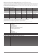
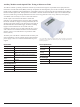
GPS (Option 0031), (Models MS2036/38C only) Requires external GPS antenna
Built-in GPS provides location information (latitude, longitude, altitude) and Universal Time (UT) information for storage
along with trace data so you can later verify that measurements were taken at the right location. The GPS option requires a
separately ordered magnet mount GPS antenna (2000-1528-R), which is configured with a 15 foot (~5 m) cable to mount
outside on a metallic surface. Frequency accuracy is enhanced for the Spectrum Analyzer when Options 0025 Interference
Analyzer and 0027 Channel Scanner are engaged.
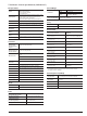
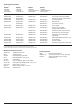
Setup
On/Off, Antenna Voltage 3.3/5.0 V, GPS Info
GPS Time/Location Indicator
Time, Latitude, Longitude and Altitude on display
Time, Latitude, Longitude and Altitude with trace storage
High Frequency Accuracy
Spectrum Analyzer, Interference Analyzer, CW Signal Generator when GPS Antenna is connected < ± 50 ppb with GPS On, 3 minutes after
satellite lock in selected mode
GPS Lock – after antenna is disconnected
< ± 50 ppb for 3 days, 0 °C to 50 °C ambient temperature
Connector
SMA, female
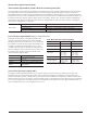
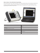
Balanced/Differential S-Parameters, 1-port (Option 0077)
As an alternative to a sampling oscilloscope, verifying the performance and identifying discontinuities in high-data-rate
differential cables is now possible with the VNA Master. After a full two-port calibration, connect your differential cable
directly to the two test ports and reveal the S
d
1
d
1
performance, which is essentially differential return loss, or any of the other
differential S-Parameters, S
c
1
c
1
, S
d
1
c
1
, or S
c
1
d
1
. With optional time domain, you can convert frequency sweeps to distance. This
capability is especially valuable for applications in high data rate cables where balanced data formats are used to isolate noise
and interference.
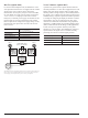
Distance Domain (Option 0501) (included in Time Domain Option 0002)
Distance Domain Analysis is a powerful field test tool to analyze cables for faults, including minor discontinuities that may
occur due to a loose connection, corrosion, or other aging effects. By using Frequency Domain Reflectometry (FDR), the
VNA Master exploits a user-specified band of full power operational frequencies (instead of DC pulses from TDR approaches) to
more precisely identify cable discontinuities. The VNA Master converts S-parameters from frequency domain into distance
domain on the horizontal display axis, using a mathematical computation called Inverse Fourier Transform. Connect a
reflection at the opposite end of the cable and the discontinuities appear versus distance to reveal any potential maintenance
issues. When access to both ends of the cable is convenient, a similar distance domain analysis is available on transmission
measurements.
Option 0501 Distance Domain will improve your productivity with displays of the cable in terms of discontinuities versus
distance. This readout can then be compared against previous measurements (from stored data) to determine whether any
degradations have occurred since installation (or the last maintenance activity). More importantly, you will know precisely
where to go to fix the problem and so minimize or prevent downtime of the system.